Facebook
 Google
 GitHub
 Linkedin
Vibration-Proof Capacitor Technology
To verify that components are sufficiently protected against vibration damage, we must first set ourselves a standard of acceptability.
Many of us will have seen the effects of excessive vibration on equipment, ranging from abnormal wear and loosened fixings to actual breakage of components. Mechanical equipment can be made immune by traditional methods such as locking components down with extra fixings or by deliberate isolation of sensitive areas using anti-vibration mountings. However, when electronics is introduced, there can be thousands of small components that may be susceptible to damage.
Today, vehicles are the prime example of a relatively hostile environment for shock and vibration in which we are packing all kinds of electronics, in everything from high power electric motor control through automated driver assistance systems to infotainment. The latest drive systems even include complex electronics in wheel hubs – in the ‘unsprung mass’ of the vehicle where mechanical environmental stress is most severe.
In vehicles and many other consumer products, electronics is often critical to safety and therefore must be highly reliable, but at the same time the lowest possible cost. However, for immunity to vibration damage, the traditional aerospace methods of ‘over-engineering’ are not feasible and solutions must be found that allows mass-produced components to meet the relevant specifications.
Setting Standards
To verify that components are sufficiently protected against vibration damage, we must first set ourselves a standard of acceptability. This is a difficult task as vibration is often quite random in nature and varies with conditions and time. In some environments, such as in industry, vibration effects often originate from rotating machinery and can be quantified to a degree but in other areas such as automotive, there is a multitude of sources from the traction system and from the road surface. Automotive OEMs have exhaustive testing regimes on test tracks with standardized rough surfaces, but the expectation is that electronic subsystems and their components are already evaluated and proven to be immune to some standard. By definition, random vibration cannot be standardized so a common technique is to apply sinusoidal excitation, swept over a frequency range with monitoring to look for mechanical resonances of components.
The vibration input then is set to dwell at these frequencies for a period, to determine if a failure occurs. Continuous sinusoidal swept vibration excitation is also the basis for the concept of ‘endurance (proving) by sweeping’. IEC 60068-2-6: 2008 is a standard for sinusoidal vibration testing methodology which also gives some suggested test levels and durations.

Figure 1: Relationship between displacement, velocity and acceleration for a sinusoid
Vibration Test levels
The intensity of pure sinusoidal vibration can be expressed in three ways which are mathematically related; maximum amplitude or displacement, maximum velocity and maximum acceleration. Figure 1 shows the relationship between the quantities normalized to 1Hz derived from the fact that velocity is the differential of displacement with time and acceleration is the differential of velocity with time.
Maximum velocity occurs when the sinusoid crosses zero and maximum acceleration is at the peak of the waveform. Remembering that the differential of sine is cosine, that is, a 90-degree phase shift and that a further differentiation is a further 90-degree phase shift helps to visualize this. The three plots in Figure 1 are equivalent so any could be used to define the vibration intensity at a particular frequency and it is convenient to quote a constant quantity, acceleration, as a specification. However, for constant acceleration, displacement increases as frequency decreases and at some point will be impractical for test equipment to maintain so it is common to see specifications that call for constant displacement vibration up to a specified ‘cross-over’ frequency and then constant acceleration from there to the maximum frequency.
IEC 60068-2-6: 2008 mostly concerns definitions of terms and methodology but does give some suggested test conditions. The sweep rate for example is specified to be exponential; one octave, or a doubling of frequency every minute, with a tolerance of +/-10%. Lower frequency in the range should be chosen from arbitrary set values; 0.1, 1, 5, 10, 55 or 100Hz and upper frequency should be chosen from 10, 20, 35, 55, 100, 150, 200, 300, 500, 1000, 2000 or 5000 Hz. A table in the standard shows test durations with a typical case of a 10Hz to 5,000Hz sweep repeated 100 times taking about 30 hours. Up to 10Hz, a constant displacement amplitude is typically specified and above 10Hz, constant acceleration. However, this cross-over frequency may need to be higher if the amplitude demanded at that frequency is beyond the test equipment capability. Where resonances are found, the standard suggests a dwell time of 10 min, 30 min, 90 min or one hour.
IEC 60068-2-6: 2008 does not prescribe exact vibration intensity levels and a number of sweep cycles but gives examples as shown in Table 1, derived from the standard. Cross-over frequency is set to be between 58Hz and 62Hz. Amplitude or displacement specification is used below the crossover frequency and acceleration above. Acceleration is given in m/s2, to convert to ‘g’ divide by 10 for an approximate value.
Capacitors Need to be Immune to Vibration
Of all the common electronic components, capacitors are often the most susceptible to vibration damage, especially high-value electro-lytic types which can be tall and small-diameter for minimum footprint. Typical through-hole leaded types have relatively poor performance and are often rated for a maximum of 10g or about 100m/s2 and 1.5mm peak to peak displacement over a swept frequency range of 10 to 55Hz. While this may be acceptable for non-critical commercial equipment, other applications such as road vehicles, construction equipment and agricultural machines typically require higher ratings.
A solution to this problem has been found by Panasonic in their range of surface-mount, aluminum electrolytic capacitors in their FK, FKS, FP, FN, FT, TC, TCU, TP and TQ series and also in their range of conductive polymer hybrid aluminum electrolytic capacitors in their ZA, ZC, ZE, ZK, ZKU, and ZS series. Parts in these series can be specified with high vibration capability featuring thicker internal connections, high ‘walls’ to the plastic base plate, and more supportive terminals with auxiliary contacts.
The improvement in performance is dramatic with the vibration-proof types able to withstand 294m/s2 (30g) and a peak to peak displacement of 5mm with vibration excitation from 5 to 2000Hz. Tests were performed in the X, Y, and Z axes for two hours each with no failure. The high vibration specification of these parts is complemented by automotive AEC-Q200 compliance and high endurance ratings, typically 10,000 hours at 105°C, 4000 hours at 125°C and 2000 hours at 145°C depending on the series
.
Conductive Polymer Hybrid Aluminum Technology Complements High Vibration Specifications
There is most risk of vibration damage to capacitors in applications where high μF values are used where the parts are physically large, often with many paralleled. Examples would be in DC-link connections in inverters or motor controllers or output filters in high power AC-DC and DC-DC converters. However, in these applications, especially at high switching frequencies, the capacitance value itself is often not the critical parameter as long as it is higher than minimum value for bulk energy storage. More important is the equivalent series resistance (ESR) and consequent ripple current handling capability of the components. High-frequency ripple current through capacitor ESR produces ripple voltage which is often critical to converter performance.

Figure 2: General construction Panasonic anti-vibration SMD capacitors
| Number of sweep cycles in each axis | Application examples | |||
| Amplitude Frequency | 0.35mm or 50m/s2 | 0.75mm or 100m/s2 | 1.5mm or 200m/s2 | |
| 10 to 55 Hz | 10 | 10 | Large industrial power plant, heavy rotating machinery, steel rolling mills, large merchant and navy ships. | |
| 10 to 55 Hz | 10 | 10 | General purpose land based and land transport, fast small marine craft (naval or civil) and general aircraft use. | |
| 10 to 2000 Hz | 10 | 10 | Space launchers (200m/s2). Engine mounted components in aircraft | |
| 55 to 500 Hz | 10 | 10 | Application as for 10Hz to 500Hz but applicable to small rigid components with no resonance response at frequencies below 55Hz. | |
| 55 to 2000 Hz | 10 | 10 | Application as for 10Hz to 2000Hz but applicable to small rigid components with no resonance response at frequencies below 55Hz. | |
| 100 to 2000 Hz | 10 | 10 | Application as for 55Hz to 2000Hz but applicable to very small components of very rigid construction for example encapsulated transistors, diodes, resistors, capacitors and integrated circuits | |
Table 1: Examples of vibration intensity and sweep cycle number for categories of application from IEC 60068-2-6: 2008
| DC-Link 12V | ||
| Radial type AI Capacitor | Panasonic Hybrid ZS Series | |
| Item | Φ 16 x 25mm4pc 2200μF, 25V | Φ 10 x 16mm3pc 560μF, 25V |
| Volume | 100% (20,000mm3) | 20% (3885mm3) |
| Total ESR (100kHz, 20°C) | 3mΩ | 2.8mΩ |
| Total Ripple rating | 11 Arms | 12 Arms |
Table 3: Case study, DC-link application with standard and conductive polymer capacitors
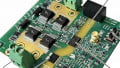
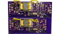
‘Standard’ electrolytic capacitors can have good ESR and ripple current ratings but the Panasonic conductive polymer hybrid aluminum types can have better ratings for smaller can sizes with better ripple voltage performance. For example, in a 12V DC-link application, if the specification requires a minimum of 1500μF with an overall ESR of 3 milliohms and 11 Arms ripple current, this can be achieved with four standard electrolytic capacitors Φ 16mm x 25mm or three Panasonic ZS series conductive polymer hybrid types Φ 10mm x 16.5mm, at just 20% of the volume and a fraction of the weight (Figure 3). Vibration resistance is also greatly enhanced by the Panasonic anti-vibration features along with the reduced height, volume and weight.
Conclusion
Applications, where vibration resistance is critical, are becoming more common and manufacturer Panasonic is responding with vibration-proof components in their capacitor ranges. Specifications for acceleration and displacement typically meet the most onerous requirements and the Panasonic conductive polymer hybrid aluminum technology can any way yield smaller and lighter components. As added benefits, compared with standard electrolytic types, the technology has better stability, longevity, reliability, safety, and life-cycle cost.
Related Content