Facebook
 Google
 GitHub
 Linkedin
Using GaAs Diodes to Reduce Cost in High Power LLC Converters
GaAs power diodes are wide bandgap semiconductor devices that exhibit excellent performance at about 70% of the cost of Silicon Carbide (SiC). In a previous article in this magazine in April 2021, it was demonstrated how GaAs diodes were able to offer system performance levels on a par with SiC in a 10kW Phase Shifted Full Bridge converter. This article extends this work to benchmark the performance of GaAs, SiC, and Hyperfast Silicon diodes in a 10kW LLC converter, a topology also commonly used for high-efficiency EV charging.
LLC Converter and Diode Types
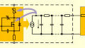
The LLC is a popular topology that offers zero voltage switching for the primary side bridge transistors, Figure 1. It allows high switching frequencies to be used whilst maintaining excellent efficiency levels since switching loss in the primary MOSFETs is minimal. On the secondary side, power loss is incurred in the output rectifiers and the nature of this loss depends on the static and dynamic characteristics of the diodes used. The dynamic behavior of the diodes (Qrr and body capacitance) also influences other aspects of the converter behavior.

Figure 1. LLC Topology. Image used courtesy of Bodo’s Power Systems
For the work in this article, similarly rated SiC, GaAs and Hyperfast Silicon diodes were benchmarked as output rectifiers (D1-D4) for the 10kW LLC. These different diode types have differing static and dynamic behaviors:
SiC
This is unipolar technology and has effectively zero reverse recovery loss, Qrr. Losses will be incurred due to the forward conduction drop and to a lesser extent the diode non-linear parasitic body capacitance. The forward conduction drop has a positive temperature co-efficient and therefore diode conduction loss will increase with temperature.
GaAs
This is bipolar technology so has a small but finite Qrr. Losses will be incurred due to the forward conduction drop and the interaction of Qrr in the operation of the converter. Note that the parasitic body capacitance is significantly lower than that of SiC. The Qrr and forward voltage drop have only a small temperature dependence.
Hyperfast Silicon
This is also bipolar technology but with significantly higher Qrr than GaAs. As temperature increases, forward conduction drop reduces, and Qrr increases significantly. For any reasonable switching frequency, diode dynamic behaviour causes degradation in performance at higher temperatures.
10kW LLC Prototype
A 10kW LLC prototype was designed to allow practical benchmarking of the three diode types. The system was designed to operate from an 800Vdc input, 100kHz to 200kHz switching frequency and develop an output voltage from 400V to 600V with a maximum output power of 10kW. The system design parameters are:
- Primary series inductance, LS=24μH
- Primary referenced magnetizing inductance, LMAG=129μH
- Primary series capacitance, CS=70nF
- Primary turns, NP=11 and secondary turns, NS=7
Low loss custom magnetics were fabricated for the prototype and the design parameters result in a system with a series resonant frequency of 123kHz. Operation of the converter from 100kHz to 200kHz will allow for examination of the performance both above and below resonance. Operation below resonance allows for natural commutation of the output diodes with low di/dt whereas above resonance operation will result in an increase in the output diode di/dt. The magnitude of Qrr and its effects on the converter performance depend on di/dt of the diode and it is therefore useful to examine how the overall performance changes in these modes of operation with the different diodes. In the prototype hardware, diode di/dt varies from about 28A/μs below resonance to about 100A/μs above resonance. Note that a typical hard-switched topology would subject diodes to di/dt levels closer to 1000A/μs.
Waveform Benchmarking
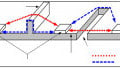
To help understand the differences in diode behaviour in the LLC in practice, the transformer primary current and secondary current in the converter were captured with an input voltage of 800Vdc, 100kHz switching frequency and 575V/17A/10kW load on the output.
Figure 2 shows that the GaAs and SiC based current waveforms are very similar and are typical for below resonance operation. In the case of Hyperfast Silicon, the impact of diode Qrr on the measured currents is clear with the secondary current changing polarity at the end of the resonant pulse before settling back to zero. During this Qrr period, the current in the primary resonant tank drops below where it would normally be with GaAs and SiC and this represents additional power dissipation incurred by the output rectifiers due to the Qrr. In the case of the Hyperfast Silicon, the output rectifiers failed shortly after the waveform was captured, most likely the result of the extra diode dissipation heating the part, leading to increased Qrr which then leads to greater heating and thermal runaway.

Figure 2. Primary (Blue) and Secondary (Red) Currents, 800V Input, 100kHz, 573V/17A/10kW Output. Image used courtesy of Bodo’s Power Systems
System Power Loss (GaAs and SiC Only)
The conversion efficiencies of the 10kW SiC and GaAs based LLC prototype are very similar, peaking at around 98% which makes benchmarking a challenge. A useful way to compare performance in these cases is to plot the overall power loss as a comparison metric instead. Figure 3 shows the measured overall loss in the 10kW LLC as a function of the DC output operating point, all with an 800Vdc input and 100-200kHz switching frequency. The green line in the figures shows the boundary of operation between above and below resonance. It is interesting to note that the boundary curve maps directly onto a point of inflexion in the power loss contours. This indicates that operation above resonance increases power loss in the converter, irrespective of the diode type used.
From the power loss plots, it is possible to see that performance with GaAs and SiC is very similar. Both technologies support highly efficient operation above and below resonance and over a similar output operating range. At very light loads, GaAs results in lower overall power loss, possibly as it has lower body capacitance than SiC. At higher power levels, the small Qrr related loss in the GaAs part leads to a lower overall loss in SiC technology.
The power loss difference at three key operating points is tabulated in Figure 4 and shows how close GaAs performance is to that of SiC. When driving 10kW output power at 578V output, the difference in system power loss between the SiC and GaAs solutions is only 13W.
Note that the Hyperfast Silicon diodes failed quickly during benchmarking tests, and it is believed that they suffered excessive heating because of their Qrr which is also strongly temperature dependent. The measurements and observations so far indicate that Hyperfast Silicon is not a contender for high frequency, high power resonant applications. A similar conclusion was drawn in our Bodo’s article in April 2021 with operation of the Hyperfast Silicon parts in a 10kW PSFB running at 100kHz.


Figure 3. Power Loss Contours for 10kW LLC. SiC Solution (Left), GaAs Solution (Right). Image used courtesy of Bodo’s Power Systems
Measurement Accuracy
Benchmarking of diode performance in the 10kW LLC application requires accurate measurement of system input and output powers. Whilst accurate test equipment was used to perform the measurements detailed in this report, measurements will encompass uncertainty which can make comparison of small differences and the conclusions drawn from them inaccurate. For the work presented in this article, component operating temperatures were also monitored, and the trends in temperature observed correlate well with the differing power levels measured.
| Point | Frequency | Diode Type | Output Voltage and Current | Output Power | Total Power Loss | Efficiency (%) | Power Loss Difference |
| (kHz) | (V) / (A) | (kW) | (W) | (%) | (W) | ||
| 1 | 100 | GaAs | 578/17.3 | 10 | 226 | 97.8 | 13 |
| SiC | 577/17.4 | 10 | 213 | 97.9 | |||
| 2 | 130 | GaAs | 503/19.9 | 10 | 241 | 97.6 | 31 |
| SiC | 503/19.9 | 10 | 210 | 97.9 | |||
| 3 | 160 | GaAs | 451/22.2 | 10 | 301 | 97.1 | 43 |
| SiC | 450/22.2 | 10 | 258 | 97.5 |
Figure 4. Performance Comparison at Key Operating Points. Image used courtesy of Bodo’s Power Systems
Conclusions
The impact of power diode characteristics on the system level performance of a converter depends on many parameters including topology, operating frequency, and temperature. In the case of high frequency resonant converters, diode dynamic characteristics influence an important part of the loss budget. The experimental work described in this article demonstrates that the very low and stable Qrr offered by new GaAs power diodes allows for LLC system performance levels very close to those of SiC. Importantly, the cost of these GaAs diodes is only around 70% of equivalent SiC parts, offering the designer an ideal opportunity to trade off a small performance reduction for a significant cost saving.
This article originally appeared in Bodo’s Power Systems magazine.