Facebook
 Google
 GitHub
 Linkedin
Substation Grounding Basics: Step, Touch, and Transferred Voltages
Learn about Earth potential gradients and shock situations in substations.
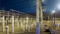
The conduction of high currents to ground in substations due to atmospheric disturbances or equipment failures generates potential gradients on Earth’s surface that are a threat to the safety of persons and animals in the surroundings.
Grounding Grid Design Criteria
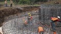
The performance of a grounding grid in a substation involves criteria related to the electrical response of one or more electrodes immersed in the Earth.
Currents on the order of thousands of amperes produce high potential gradients in the vicinity of the points of contact of the substation grid to the Earth. If people or animals touch places having different potentials, they may suffer an electric shock.
The most critical design criteria for grounding grids are:
- Avoid hazardous potential gradients in the vicinity of grounded electrical structures during fault conditions
- Obtain a ground resistance lower than a preset value. It is vital to understand that a low ground resistance value does not ensure the safety of people standing on the earth above the grounding grid or in the surrounding area
The design of the grounding grid requires the computation of the maximum step, touch, and transfer voltages that a person can withstand.
The Electric Potential
A charged particle inside an electric field has potential energy because of its interaction with the field. The electric potential in a location is the potential energy per unit charge placed at the location. The electric potential unit is the volt, denoted by V, in honor of the Italian scientist Alessandro Volta (1745–1827).
If a charge moves from one point (P1) to another point (P2) along any path, the electric field experiences an electric potential difference – or voltage – between P1 and P2.
To ascertain the amount of work required to move the charge from P1 to P2, we must have a reference level from which we can begin to find the energy expended. Usually, this reference position is at a considerable distance from all charges, and the electric potential at this distance is 0 V, as a matter of convenience.
Any point may be a reference position, and the reference potential magnitude can be any value. Frequently, in circuit analysis, the Earth is the reference of potential with a value of 0 V.
Earth Potential Gradients
The total value of the ground resistance of an electrode may be described by adding resistances in series from the electrode to a point at an infinite distance from the electrode. The magnitude of these resistances is inversely proportional to the distance from the electrode. The larger resistances are near the grounding electrode; the rate of the total resistance’s rise decreases as we move away from the electrode.
When a current (I) from a ground fault or an atmospheric discharge goes through the grounding electrode, it flows through all resistors to infinity. According to Ohm’s law, this current creates a voltage drop of magnitude V = IR across each resistance.
The potential at every point on the Earth may be computed by adding the voltage drops from the electrode to infinity, taking the grounding electrode as a reference position with a reference potential of 0 V.
In practice, the potential is measured on Earth’s surface, using techniques such as the fall of potential method.
Figure 1 shows how Earth’s potential – with respect to the grounding electrode – increases as we move outward from the electrode.

Figure. 1 Potential profile with the grounding electrode as the reference position. GPR stands for ground potential rise. Image courtesy of Prof. J. H. Briceño
The rate of rise of the potential is high in points close to the electrode but decreases as we move away, just like resistance, which is reasonable since Ohm’s law is a linear equation. Therefore, most of the potential resulting from the current I appears on Earth’s surface close to the grounding electrode.
As seen in Figure 1, the potential starts at 0 V and reaches the maximum value at infinity.
In grounding analysis, the common practice is to use infinity as the reference position for Earth’s potential rather than the grounding electrode. Then, the potential will be at its maximum value at the electrode and will decrease as we move away from it, to reach a value of 0 V at infinity.
The ground potential rise (GPR) is the maximum electric potential that the grounding electrode may reach. Numerically, it is the product of current I times the electrode resistance to ground Rg.
Figure 2 shows a typical substation structure grounded only at its foundation and a curve of Earth potential vs. radial distance. Notice that the potential on the Earth’s surface is at its maximum at the facility, lessening as the distance increases.

Figure 2. Potential profile with infinity as the reference position
The curve of potential in Figure 2 is a mirror image of the curve seen in Figure 1. This is caused by the exchange of the reference positions.
In practice, with a single rod, the potential will be negligible after a distance of about 20 m, showing that infinity is closer than we might think.
The curve of potential goes around the grounding electrode, producing a “potential funnel” surrounding the electrode.
Some publications exhibit the values of potential on the lower portion of the ordinate axis, as shown in Figure 3. This could cause confusion, as the usual practice is to display positive values on the upper portion of the ordinate axis.

Figure 3. Another way of displaying the potential profile with infinity as the reference position
Figure 4 shows a potential contour based on Figure 3. This potential contour is a projection of the “potential funnel” on Earth’s surface. The circles are equipotential lines because they join all points with the same potential.

Figure 4. Equipotential lines on Earth’s surface
With a symmetrical electrode – and constant soil resistivity – the equipotential points on Earth’s surface form a set of concentric circles. In practice, the contours are never perfect circles; their shape varies depending on several factors, and the ones shown are for illustration only.
Subtraction of the potentials of two adjacent circles gives the potential difference — or voltage — between them.
Step, Touch, and Transferred Voltages
Figure 5 shows three typical shock situations analyzed when designing grounding grids in electrical substations. Recall that the potential profile shows up when injecting a current I into the grounding electrode.

Figure 5. Step, touch, and transferred voltages. Image courtesy of Prof. J. H. Briceño
Situation 1 is the step voltage. When people walk towards the grounding electrode, their feet “see” different potentials. The potential difference is the step voltage. The standard length of a step is 1 m for people and 1.5 m for animals.
Step voltage can be dangerous under certain circumstances. Still, several studies show that, although painful, it is less hazardous than other types of contacts because the current circulating from one foot to the other does not pass through the vital organs of the body, like the heart. However, the step voltage can cause the person to fall, triggering a current flow through the chest and putting vital organs at risk. It could also affect a person working or lying on the floor.
In animals, the greater separation between the extremities causes higher voltages, and, due to their anatomical constitution, the heart is in the current’s path.
Figure 6 shows a person walking on Figure 3’s curve towards the grounding electrode. It is clear that the step voltage increases as the person approaches the electrode, the worst case being when they touch. This is due to the steeper slope of the curve on the Earth near the electrode.

Figure 6. Step voltages as the person approaches the grounding electrode
In Situation 2, a person touches a grounded structure having their feet at a potential other than that of the structure’s ground. This situation is the touch voltage. As seen in Figure 5, the potential at the assembly is the GPR. The maximum distance that a person can reach is 1 m, so that is the separation between the hand and foot contacts.
Situation 2 is more dangerous as the current circulates through vital organs, including the heart.
Situation 3 is the transferred voltage. This situation is a particular case of touch voltage that happens when the person is far from the grounding electrode and touches a metal element in contact with the electrode. Here, the person “sees” a potential difference equal to or exceeding the GPR of the substation. The potential difference is more significant in Situation 3 than in the other two.
An essential criterion for safety is having the magnitudes of step voltage and touch voltage below the threshold at which injury may occur.
A Review of Touch, Step, and Transferred Voltages
High currents through the substation grid produce potential gradients on the Earth’s surface that may endanger the lives of people and animals nearby.
A grounding grid must control the potential gradients and create adequate ground resistance.
The ground potential rise (GPR) is the maximum electric potential that a grounding electrode may reach. In grounding practice, the reference position for electric potential is infinity. The potential at the electrode is the GPR, and it decreases in a radial direction, reaching 0 V at infinity.
Three typical shock situations analyzed when designing grounding grids are step, touch, and transferred voltage. Touch voltage is the most dangerous because the current passes through vital organs in the body. Transferred voltage is a particular case of touch voltage in which the body may be subjected to the full GPR.
The design of a grounding grid must pursue safe values of step, touch, and transferred voltage.