Facebook
 Google
 GitHub
 Linkedin
System-Simulation for Virtual Power Modules
This article highlights the importance of simulation in designing and optimization of power modules and its advantages over conventional evaluation.
Designing, dimensioning and optimization of power modules and its management is a complex task. Electronic designers of power modules are focused today on targets like: cost reduction, increase of power density, increase of product reliability and reduction of parasitic elements. These targets will result in a negative impact on the overall performance of switching behavior and switching loss of power semiconductor
Different fields of application (automotive, IoT, medical) are driving the need to design and optimize the complete power system with respect to the performance of the power module and at the same time keeping the cost low and design a system with a high degree of interchangeability. This increase of the requirements and a mixed signal architecture of power modules make the design process a difficult task.
Optimization often results in an increasing number of interacting sensors which adds another level of complexity to such a feedback control system. At the same time, all industries want to miniaturize their devices and the dimensions of power modules have to shrink with less safety space between the sensitive parts of the circuit. Flexibility and reliability often drives the demand to build platforms of power system, which can be reused for multiple applications very quickly. Platforms are designed for a much wider specification and they need to operate in all corner cases.

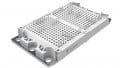
Figure 1: Example of a system which includes a power module, a controller and a load
Conventional Evaluation
The conventional way to evaluate and verify all requirements of a power system was to design the analog and the digital part of the circuit in its respective departments and working in separate teams. Each of these teams achieved the proposed specification and finally integrated all the parts in a hardware prototype to test it. Many errors were only found when the first set of hardware prototypes was build and required modifications had to be done in the different (analog and digital) departments. These iterations would lead to redesigns and building of multiple prototypes.
This process of physical prototypes is time-consuming and requires an increasing number of measurements for different corner cases.
To overcome the cost and time spend on multiple prototypes and measurements a mixed signal simulation of the complete system is required to simulate the interaction of the analog and digital part of the system. In such a simulation the goals of performance, reliability, yield and flexibility should be covered and evaluated before the first physical prototype is built.

Figure 2: Traditional analog/mixed signal design flow
The Need for Simulation
Cadence introduced a new comprehensive simulation to analyze further partial aspects of the power module and its management in different kind of simulations. First, you could simulate different analog designs to prove not only that it works as it is expected, but also to prove that they are reliable for production. The simulation covers manufacturing tolerance variations, different ambient temperatures during operation, the full operating range as specified, and aging of electrical components. After stabilizing the analog or digital implementation of the design, it has to be integrated in a system-wide simulation with all integration parts of the power design together.

Figure 3: Example showing stress and component tolerances (Monte Carlo Analysis) to improve overall reliability
Disadvantages of Conventional Evaluation
Power systems are complex and often developed by teams with several people or in different departments. This means that different parts of the power module are developed independent of each other, without the interaction between the analog part, digital part, embedded regulator software, and consideration of different ambient conditions.
Only when individual parts are assembled in a hardware prototype and a physical verification is carried out differences or gaps occur regarding the specification. Some errors found while validating the prototype will require massive changes to the design block. Necessary changes discovered late in the design process are very expensive, because the design has to be performed again and all time spent so far is lost. It is very cost intense to introduce changes to the specification after the start of development and communicate the impact to all members of the development team.
In general, the cost of changes to the specification will be higher, when they occurred in advanced stages of the design process. In order to minimize the cost of changes and not delay the planned start of production, an early merge of the partial developments in a single simulation environment makes sense.
Advantages of Simulation
Iterations in the development process can be reduced if a parallel methodology is used in which information between departments is exchanged at any time and is available to all members at the same time. Individual development results can be exchanged and their influence on the overall system is recognized at the earliest stage possible. The results can be used immediately for improvements or changes.
Such exchange of information across teams requires compatible tools and appropriate interfaces. Only when blocks of the other departments can be used quickly, easily and safely in other departments the methodology is accepted by the users. For the electronic developers, it is advantageous if they can integrate other modules of the drive circuit as a function block in his simulated environment familiar to him. In this virtual world, the software control, the management and the power module can now be optimized.

Figure 4: Use of PSpice Systems Simulator to match simulation environment for electrical and physical system
In the case of complete new developments, an early simulation also provides results which enable the specification to be checked.
Specifications have frequently gaps or undefined states because some things were not thought of in the preview or not all requirements were known at the beginning. If these questions arise during the simulation, the points can be clarified and the specification is supplemented or clarified.
A system simulation flow consists of a combination of MATLAB/Simulink and PSpice in a bi-directional co-simulation. On the first hand, MATLAB/Simulink is a platform for multi-domain simulation and model-based design of dynamic system, which offers a massive simulation library for different application fields like automotive, medical, IoT, etc.
On the other hand, PSpice is a full-featured ISO 26262 certified analog simulator with support for digital elements to help solve virtually any electrical design challenge, where it is possible to use a big set of very new models, as most IC vendors provide compatible models. Using both together in a co-simulation allows to exhibit the non-linearities, delay and other real-word effects for the electrical components in the system simulation. You can even visualize the PSpice results in MATLAB as well as use all MATLAB mathematical functions in PSpice to debug the system level error much more easily avoiding processing this manually, which usually prone to error.
This bi-directional co-simulation between the behavioral/mathematical MATLAB/Simulink blocks and the circuit level analog/mixed signal PSpice blocks in one integrated environment allows increasing quality, flexibility and reliability of the whole system. Furthermore, it lets verify that the integrated system works as the requirements and decrease the developing difficulties and the time to market of the product.
About the Author
Roberto Gandia works as an Application Engineer at FlowCAD EDA- Software Vertriebs GmbH, a distributor in Central Europe for hardware and software development tools for electronic circuits and offers solutions from several manufacturers for PCB Layout, FPGA and IC Design, thermal simulation and more. He earned his degree in Electrical Engineering at the Miguel Hernández University of Elche, Alicante, Spain.
This article originally appeared in the Bodo’s Power Systems magazine.