Facebook
 Google
 GitHub
 Linkedin
Substation Components—Part 6: Station Batteries and DC Supply
In substations, the DC system is critical for protection, control, and SCADA during AC loss. Learn about the relevant IEEE standards, choosing the right chemistry, and more.
Reliable station DC is the silent backbone of every substation. When the AC auxiliary source sags or is lost, the DC system must still trip and close breakers, power protection and control, and maintain communications long enough to put the grid in a safe state. Getting DC right is therefore a design, operations, and compliance requirement.
What the DC System Must Do
Trip and close breakers and operate lockout relays and motor operators. These actions must be available even when the AC station service is unavailable. Guidance documents for low‑voltage auxiliary systems emphasize that DC auxiliaries are a critical substation function to ensure safe operation during disturbances.
Power protection and control. Protection relays, logic, and interlocking depend on the DC bus and are explicitly recognized as part of the Protection System. NERC PRC‑005 includes the “station DC power supply associated with a protective function, including station batteries, battery chargers, and non‑battery-based DC power supplies,” placing maintenance and documentation obligations on owners.
Keep the substation visible and controllable. SCADA RTUs/IEDs, time sources, and communications often ride on the station DC (sometimes via DC/DC converters), so the DC system is fundamental to situational awareness and remote control when it matters most. The substation auxiliary guide frames these AC and DC auxiliaries together as the foundation of operability.
Nominal DC voltages commonly selected for power applications include 24 V, 48 V, 125 V, and 250 V, with use depending on device ratings, distance, and fault‑tolerance requirements (for example, 125 Vdc for trip/close circuits and 48 Vdc for communications). IEEE design practice addresses coordination, ride‑through, and component voltage ranges for such systems.
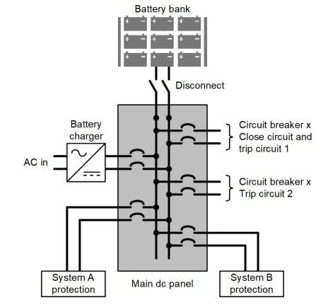
Figure 1. Typical DC system. Image used courtesy of Schweitzer Engineering Laboratories (SEL).
Battery Technologies
Lead‑acid remains the dominant technology in most North American substations. IEEE 485 is the sizing practice for stationary lead‑acid in float service; it structures DC duty profiles and prescribes how to translate those loads into required ampere‑hour capacity. Complementary guidance for DC system design, including charger and distribution considerations, appears in IEEE 946. These standards remain the primary references for control‑power battery design.
Within lead‑acid, users choose between vented (VLA) and valve‑regulated (VRLA) types. VRLA can reduce ventilation and maintenance needs but demands tighter temperature and charge control; installation and maintenance practices are covered in IEEE 1187 and IEEE 1188. VLA offers proven life and tolerance to abuse at the expense of more stringent ventilation and maintenance. Organization-specific environmental controls, life expectations, and failure modes should guide the selection process.
Nickel‑cadmium (Ni‑Cd) is favored in harsh environments and for wide temperature operation. Ni‑Cd exhibits a flatter discharge curve and tolerates deep discharges and low temperatures better than many lead‑acid designs. For Ni‑Cd, use IEEE 1115 for sizing and IEEE 1106 for installation, maintenance, and testing.
Lithium‑ion is emerging in substation control‑power applications, primarily where footprint, weight, or high cycle counts are decisive and where an integrated battery management system (BMS) can add value. Because Li‑ion behavior, safety engineering, and qualification differ significantly from legacy chemistries, two references are key: IEEE 1679.1, a technology‑agnostic evaluation guide for lithium‑based stationary batteries, and IEC 62619, the safety standard for industrial Li‑ion cells and batteries, including stationary uses. In North America, UL 1973 is commonly specified for stationary battery system safety. These documents help define selection, safety, and compliance criteria, but note that IEEE 485/1115 sizing methods are not directly transferable to Li‑ion without vendor‑specific BMS considerations.
Battery Sizing
Sizing begins with the loads. IEEE 485 (lead‑acid) and IEEE 1115 (Ni‑Cd) walk through the process of classifying DC loads—continuous, non‑continuous (time‑limited), and momentary—and assembling a duty cycle that reflects both normal operation and credible events (faults, reclosing sequences, black‑start steps, etc.). The standards then specify how to calculate the required capacity to meet the duty profile at a selected end‑of‑discharge voltage per cell and ambient temperature.
Key steps to include in any station battery calculation:
Build the duty cycle. Tally the continuous loads (relays, communications, RTU/IEDs), time‑limited loads (panel lighting, motor operators that may run for tens of seconds), and momentary loads (trip/close coil energization, lockout relays). Be careful to include worst‑case concurrence—such as multi‑breaker trips for bus protection.
Pick the cell count and minimum voltage. Select an end‑cell voltage appropriate to the chemistry and duty profile. That choice drives the cell count needed to keep all devices inside their operating voltage windows at the end of the duty cycle. IEEE 946 discusses allowable device voltage ranges and their influence on system design.
Apply temperature and ageing allowances. Capacity must be corrected for expected ambient temperature and for life‑end conditions (aging). The standards discuss how to apply margins; specific percentages are policy‑ and vendor‑dependent and should not be assumed without reference to the governing standard and procurement specifications.
Define autonomy. The autonomy period—how long the DC system must support continuous loads and still deliver required operations—should trace back to utility or owner policy, risk analysis, and applicable regulatory commitments. Traction and utility specifications often call for many hours of autonomy plus assured trip/close operations after that period; each project should align with the documented requirements rather than relying on rules of thumb.
Remember that the DC architecture and device tolerances shape the load profile. For example, a single fault can energize multiple trip coils, and certain inverters or DC‑DC converters may impose inrush transients that influence battery and charger sizing; IEEE 946 addresses these interactions and their impact on system performance.
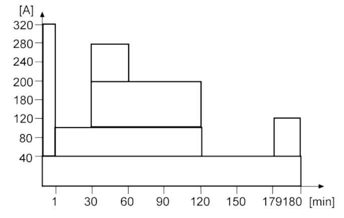
Figure 2. Example of a duty cycle. Image used courtesy of ABB.
Chargers, Redundancy, and Monitoring
Chargers are not just “battery maintainers”—they are the primary DC source during normal operation. IEEE 946 covers charger/rectifier sizing and regulation, ripple considerations, ground detection, and distribution. Good practice is to size the charger(s) for the entire continuous load plus the required recharge current within a specified time after a discharge event. Where availability is critical, use parallel redundant chargers with output isolation, coordinated setpoints, and alarms.
Redundancy should extend beyond rectifiers. Many utilities deploy two independent battery/charger/DC‑panel sections at the same nominal voltage, with a normally open bus‑tie so that a single failure does not compromise all tripping and control. This approach increases availability and simplifies maintenance; the tie can be closed under supervision when needed.
Monitoring and compliance round out a robust design. NERC PRC‑005 requires a documented Protection System Maintenance Program that includes station DC supplies, with defined activities and intervals. Utilities may adopt time‑based maintenance or qualify performance‑based intervals where permitted.
Battery monitors and ground‑fault detectors are key enablers: IEEE 1491 describes which parameters add diagnostic value (cell or unit voltage, string current, internal resistance/conductance, temperature, ripple, and ground‑fault indication) and how to specify monitoring systems. Tie alarms into SCADA so operators see degraded conditions early.
Finally, consider safety and certification—especially for Li‑ion systems integrated into control power. Beyond IEEE evaluation guidance, look for compliance to IEC 62619 (industrial Li‑ion safety) and UL 1973 (stationary battery systems), in addition to local code requirements (such as NFPA 70). These standards address abuse testing, thermal runaway mitigation, and system‑level protective functions that complement substation engineering controls.
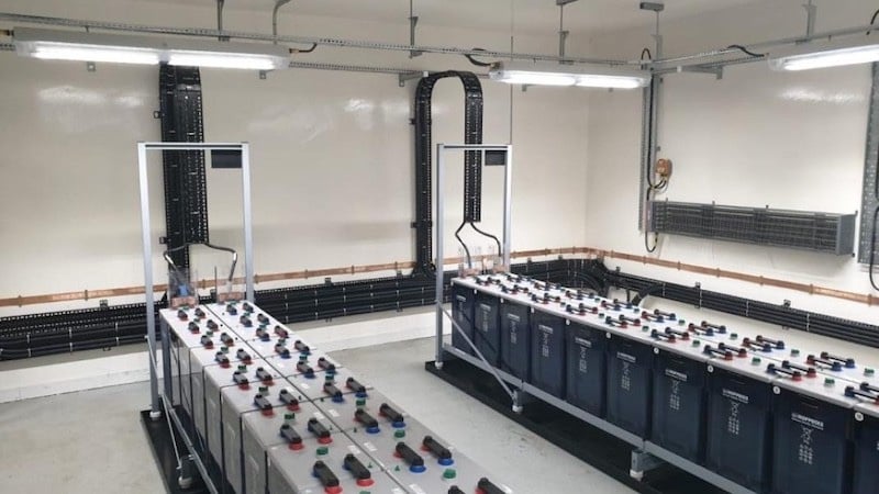
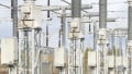
Figure 3. DC chargers installed at the substation. Image used courtesy of Dale Power Solutions.
Key Takeaways
A station DC system is more than a box of batteries: it is a coordinated system of battery technology, architecture, protection, and monitoring that must act correctly in the worst minute of a substation’s life. Lead‑acid and Ni‑Cd remain proven choices when sized and applied per IEEE 485/1115, while Li‑ion is a compelling alternative where its safety, BMS behavior, and standards compliance are fully addressed.
Charger sizing and redundancy, distribution layout, and continuous monitoring ensure overall system integrity. Adhering to current IEEE practices for DC system design (IEEE 946 and IEEE 1818) and aligning maintenance with PRC-005 enhances reliability and audit readiness—and, most importantly, ensures that protection, control, and SCADA continue to operate when the grid needs them most.