Facebook
 Google
 GitHub
 Linkedin
Semiconductor Solutions for Energy Storage Systems in Light Traction Vehicles
This article highlights semiconductor solutions using Infineon Technologies AG IGBT modules belonging to the PrimePACK™ family equipped with IGBT/FWD chips.
The requirements regarding modern light traction vehicles, such as trolleybuses and trams, gradually increase. Special focus is set to operation without trolley power supply temporarily while remaining free of emissions. Efficiency, power density, volume and weight of the system become more important. At the same time, low acoustic noise and restrictive EMI-standards have to be met.
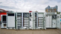
These particular requirements can be met using energy storage systems based on Lithium-Ion traction batteries or supercapacitors. To fully utilize the capabilities of the storage systems, it is necessary to employ suitable power converters to manage the flow of energy in both, charging and consuming. This correlates to DC-DC converters which have to handle substantial cyclic loads at potentially high operating temperatures. The ability to temporarily operate without the trolley power supply is a feature found more often among the requirements regarding light traction vehicles. This mode of operation is utilized within the urban areas lacking the catenary infrastructure such as historical centers. It also applies to connections between separated lines and is needed for emergency vehicle operation during power blackout as well. In addition, low-noise, high-comfort, zero-emission operation is demanded, ruling out the diesel-electric drive train as it was commonly used in the past. The sum of requirements can be met by installing an electric/electric hybrid approach. In this, traction batteries or super-capacitors are installed as energy storage systems, providing intermediate power to the electric drive train. Figure 1 is a scheme of a tram with the power converters installed on top of the train.

Figure 1: Position of the electric equipment on a tram
Inside the roof unit, the DC-DC-converter to manage the energy flow to and from the batteries is one of the power electronic subsystems. The converter is a compact, often forced air-cooled power unit. The development of electrical equipment focuses on finding the optimal solution for power converters using traction batteries or supercapacitors. To serve the demands, several criteria have to meet:1. In Trolley Mode, well-controlled charging of the energy storage from the DC trolley systems has to be possible. This correlates to an input voltage range from 400VDC to 1000VDC.2. In Battery Mode, well-controlled power flow from the battery to propulsion inverter, auxiliary converters, and vehicle battery charger are mandatory 3. In both modes, safe handling of short but repeating bursts of load up to 200kW for 60 seconds has to be possible even if exposed to relatively high temperatures with limited forced air cooling capabilities.4. Achieve high operational efficiency while occupying low volume at evenly low weight. To meet the criteria 1 and 2 and depending on the boundary conditions, there are two topologies for DC choppers to be considered. If the energy storage system operates at higher as well as lower values than the trolley voltage level, using a 2-quadrant DC-chopper is mandatory. A suitable scheme is depicted in Figure 2.

Figure 2: Topology of 2-Quadrant DC-Chopper
If the voltage of the energy storage system always stays below the trolley voltage, a buck-boost DC chopper as given in Figure 3 is most suitable.

Figure 3: Topology of a Buck-Boost DC-Chopper
In Trolley Mode, the converter works as a step-down chopper providing a voltage lower than the trolley supply to the trolleybus’ internal systems. In Battery Mode, the converter works as the step-up chopper supplying the electric systems with a voltage higher than the storage system’s output. To meet criteria 3 and 4, suitable power semiconductor devices are needed. The solution using IGBT modules within the 1700 V class needs to support sufficient current range, low conducting and switching losses as well as a robust package with low thermal resistance. In addition, a favorable cost/performance ratio on the system level is demanded.
IGBT modules belonging to the PrimePACK™ family equipped with the 4th generation of IGBT/FWD chips pose a suitable solution. This IGBT module family includes IGBTs in half-bridge topology in 1200V and 1700V classes, offering nominal currents in the range of 600A to 1400A. The modules are available with two types of durable robust packages, all equipped with an integrated NTC sensor to capture the module’s baseplate temperature.
These components, depicted in Figure 4, are dedicated to being used in heavy-duty mobile applications [1,2] and allow considering scalable designs.
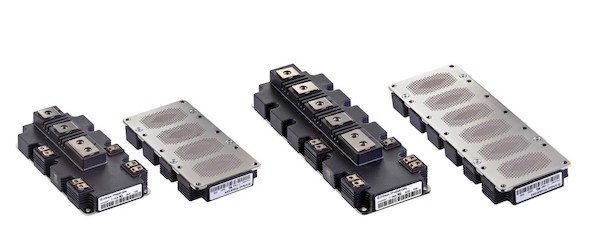
Figure 4: PrimePACK™ 2 and 3 with applied thermal interface material (TIM)
To achieve safe operation and full power utilization of the IGBT module, a suitable gate driver needs to be chosen. For evaluation, the 2ED250E12_F dual-channel IGBT-driver, as well as the booster stage MA300E17, are available to help designers develop their dedicated solution. Both devices can be seen in Figure 5. The thermal situation for the power section demands the most accurate thermal measurement to be implemented into the control strategy to exploiting the power to the maximum without exceeding the specified operating limits.
Very often, the surface temperature of the heat sink had been monitored with an external temperature sensor. Based on this feedback, the power output of the converter had been tuned by the control system. There is however a significantly higher temperature on the base plate of the IGBT modules and thus the temperature of the sensitive transistor and diode chips inside. For safety reasons, a rather conservative value of the temperature that triggers the reduction of the converter’s output power had to be chosen.
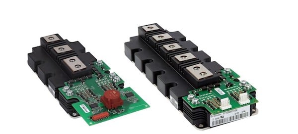
Figure 5: Dual-Channel driver 2ED250E12_F and booster stage MA300E17 mounted to the according power module
To get more accurate information, the design of monitoring the thermal load and triggering the overheating protection should use the temperature measured by the NTC inside the IGBT modules [3,4].
This approach provides a more realistic view of the thermal load of the semiconductors in the real operation. Especially if the thermal correlations between chip-temperature and NTC-reading are determined accurately, robust information for static operation can be extrapolated [3, 4].
The number of energy storage systems like traction batteries or supercapacitors in light traction vehicles is continuously increasing. It is safe to assume, that higher demand regarding the power capacity of the DC converters becomes a trend, also there is pressure to reduce their weight and size including smoothing DC chokes. To meet these requirements in the near future, new IGBT modules in the form of a 5th generation IGBT module featuring Infineon’s. XT technology offers an excellent choice.
These new modules have significantly higher performance compared to existing modules. As a consequence of lower total power losses 25 °C higher junction temperature of Tvjopmax = 175 °C, the modules feature a higher power density [5]. At least 30 % higher output power from the same footprint is expected. This allows designing higher performance converters with the same type of the IGBT module packages, thus reducing the effort for redesign and upgrade.
Furthermore, thanks to the advanced interconnection technology, the internal module structure based on the. XT technology achieves a significantly higher lifetime in terms of power- and thermal cycling load [6].
In the medium term, the focus of the evaluation is set on the application of power components based on the Silicon Carbide (SiC) MOSFET in Trench technology recently introduced [7]. Thanks to the exceptional properties of these components, especially considerably low switching losses compared to the Si IGBT modules, several improvements are expected in the properties of the DC choppers that employ such power components:
- Higher output power at switching frequencies exceeding 20 - 30 kHz while reducing the chopper’s volume
- Higher efficiency and lower energy consumption with a positive impact on the cooling system’s size and construction
- Because of the high switching frequency, substantially reduced size and weight of the passive components such as power film capacitors and the DC chokes
- Significantly reduced acoustic noise
- The cooling requirements for converters with the same output power will be significantly reduced, leading to smaller size and weight of the heat sinks and fans. Vice versa, a converter with the same size is expected to feature far higher output power
Dedicated power units are mandatory to properly operate energy storage systems, especially in sensitive mobile applications. Besides the electrical performance, power density and efficiency mater but special attention have to be paid to the consequences resulting from the cyclic load. In addition to the optimization in cooling and control of power flow, modern power semiconductor solutions allow reducing the losses which ease power dissipation in limited space. Wide bandgap materials reveal outstanding electrical performance and the higher switching frequencies can be helpful in reducing the amount of material used in magnetic components. Despite all innovations in semiconductor development, proper thermal design, accurate temperature measurement, and suitable thermal models remain an important part of the development flow for power electronic components.
About the Author
Martin Schulz, since August 2005, has worked as the Principal Application Engineering at Infineon Technologies, a world leader in semiconductor solutions that make life easier, safer and greener. Microelectronics from Infineon is the key to a better future. In the 2018 fiscal year (ending 30 September), the Company reported sales of €7.6 billion with about 40,100 employees worldwide. Infineon is listed on the Frankfurt Stock Exchange and in the USA on the over-the-counter market OTCQX International Premier.
References
- Martin SchulzPower semiconductors for Heavy Mobile ApplicationsITEC 2016, Busan, Korea, June2016
- Scott T. Allen, Martin Schulz, Wilhelm PohlOptimizing Thermal Interface Material for theSpecific Needs of Power ElectronicsPCIM 2012, Nuremberg, Germany, May 2012
- Martin Schulz, Ma XinCorrelating NTC-Reading and Chip- Temperature in Power Elec-tronic ModulesPCIM 2015 Nuremberg, Germany, May 2015
- Ziqin Zhen, Song Shen, Zhen Bo Zhao, Zeping Zhou, Xie FengAnalysis of temperature correlation on IGBT modulesPCIM China 2015 Shanghai, China, July 2015
- Martin Schulz, Raghavan Nagarajan, Dirk Brieke, Zhen Bo Zhao Application Benefits Achieved Utilizing IGBT5-Based Power Semi-conductorsPCIM China 2015, Shanghai, China in June 2016
- Karsten Guth et. al.New assembly and interconnects beyond sintering methods PCIM 2010, Nuremberg, Germany, May 2010
- Maximilian Slawinski, Tim Villbusch, Daniel Heer, Marc Busch-kühleDemonstration of superior SiC MOSFET Module performance within a Buck-Boost Conversion SystemPCIM 2016 Nuremberg, Germany, May 2016
This article originally appeared in the Bodo’s Power Systems magazine.