Facebook
 Google
 GitHub
 Linkedin
Reverse Power Feeding Enables HighSpeed Internet Access
This article highlights Texas Instruments power solution on how these interconnection points are supplied by the end customers using the same copper wires.
The demand for internet access with always higher bandwidth is increasing, as more and more data is transferred due to services which were unimaginable a few years ago. Online media centers and video-on-demand provide movies and news in high definition, thousands of internet radio stations offer music for all predilections, computer backups and photos are stored in the cloud and telephone calls are done via VoIP, just to name a few with the need for high speed. In the use of old telephone installations based on copper wires between the end user and the well-known boxes in the street, the distance between these two points basically limit the maximum speed.
Reverse Power Feed for Remote Nodes
To increase the speed significantly, the interconnection point between telecom provider and end user have to move closer supporting smaller geographic areas. It needs also to be powered, but providing a connection to the main grid is costly, so the telecom providers want to avoid this. The new standard Reverse Power Feed for Remote Nodes which is published by the ETSI (European Telecommunication Standards Institute) describes how these interconnection points are supplied by the end customers using the same copper wires which are already used for the data transfer.
This removes the need for an access to the power grid and makes it possible to decrease the distance between the interconnection point of the telecom provider and the end customer to a minimum and thereby pushing the speed. This article describes a power solution for reverse powering a single load from up to eight different inputs, seen in this context as customers.
VDSL2 goes G.fast
The majority of all subscribers are connected to the Distribution Point Unit (DPU) by copper wires. The length of this loop or last mile practically limits the potential speed. With VDSL2, which is the fastest available transfer standard based on Digital Subscriber Line (DSL) today, the loop length can be pushed up to 5000 m based on the implemented profile. With a bandwidth of 30 MHz, the data rate is up to 200 Mbit/s but it depends significant on the distance between DPU and end user. The DPU is typically placed close to a street with direct connection to the power grid which allows an easy supply of the electronics.
The new G.fast standard still uses the copper wires between DPU and end customer, but the distance needs to be below 250 m. By reducing the length of the copper wires and increasing the bandwidth to 105 MHz or even 212 MHz, the data rate can be raised up to 1 Gbit/s. In both standards, the length of the last mile directly influences the data rate and the shorter this distance, the higher the data rate. Therefore the DPU should be as close as possible to the customer.
VDSL2 to G.fast more DPUs are needed
The bottom line is that for an upgrade from VDSL2 to G.fast more DPUs are needed, which are widely distributed over an area which was previously supplied by a single DPU based on VDSL2. Each DPU needs also power and to keep the costs low, the idea is not to power it by the power grid but from the end customer. By this technique called Reverse Power Feed, several end customers power the electronic of the DPU with the same copper wires which are used for the data transfer.
Figure 1 shows the typically used topology Fiber To The distribution point (FTTdp) with the G.fast standard between DPU and end customer.
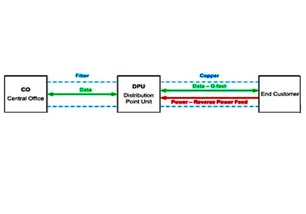
Figure 1: FTTdp Topology
The data between Central Office (CO) and DPU is transferred by fiber. The DPU is now closer to the end customer still using the copper wire and the new G.fast standard for the data transfer. Additionally, power is transferred from the customer to the DPU to power the electronics inside. The figure shows only one end customer, but usually several customers are connected to a single DPU.
The customers together have to provide the power and due to fairness it should be shared equally between all active participants. The focus of this article is the power supply inside the DPU, which has several inputs to connect the end customers and one single output to provide power the DPU.
Specification
- One isolated output with 12.0V / 1.1A
- 27..60V DC input voltage from up to eight inputs
- One converter must be able to provide the full power
- The load has to be shared equally between all active inputs
- Possibility to connect and disconnect inputs during operation
Flyback Converter
The best topology according cost and performance for this application is a flyback converter. The input and output specification is typical for telecom applications and therefore the probability to find a standard transformer is high, which keeps the cost and development time low compared to a custom made transformer.
Making sure the load is shared proportionally to usage of all active participants needs some more effort. Simply putting eight converters in parallel can only be done, if the controller provides a cycle-by-cycle current limit. The current limit is adjusted to the maximum output current of a single converter but the problem is that the output voltage of the converters is not exactly the same.
The result is that the converter with the highest output voltage due to tolerances provides the complete current and all other converters do not contribute anything. The other converters only become active, when the output current of the first converter is limited by the cycle-by-cycle current limit. Then the converter with the second highest output voltage provides also current, all other still don’t.
Cycle-by-cycle current limit prevents overstressing a single converter
Cycle-by-cycle current limit prevents overstressing a single converter but a real load sharing between several converters under all load conditions is not possible. If the controller has not this kind of current limit but only a simple overcurrent protection which switches OFF the converter at a too high current, even putting several converters in parallel is not possible. Like on the previous example, the converter with the highest output voltage will provide the complete current. But now, if it becomes too high, the converter is switched OFF instead of limiting the output current to the programmed value.
Proper load sharing
For proper load sharing, the output current needs to be measured and the duty cycle of each converter adjusted such that the output current of all active converters is the same. A discrete solution based on a bunch of operational amplifiers is conceivable, but the load share controller UCC29002/1 provides exactly the functionality needed for this application in a small SO-8 package.
A shunt is added in series to the output of each converter for measuring the output current by the integrated current sense amplifier of the load share controller. All eight load share controller communicate via a load share bus, which is an analog voltage proportional to the output current of a single converter.
Load share controller on the converter
The load share controller on the converter with the highest output voltage becomes automatically the master, all other ones become slaves. The master sets the voltage on the load share bus and the slaves adjust the duty cycle of the corresponding converter such that the output voltage equals the analog voltage on the bus.
Thereby all converters provide the same current and the load is shared equally. If converters are switched on or off, the master adjusts the voltage on the load share bus to get back to a balanced operation. Even switching off the master is no problem, as the output with the second highest voltage becomes the new master automatically.
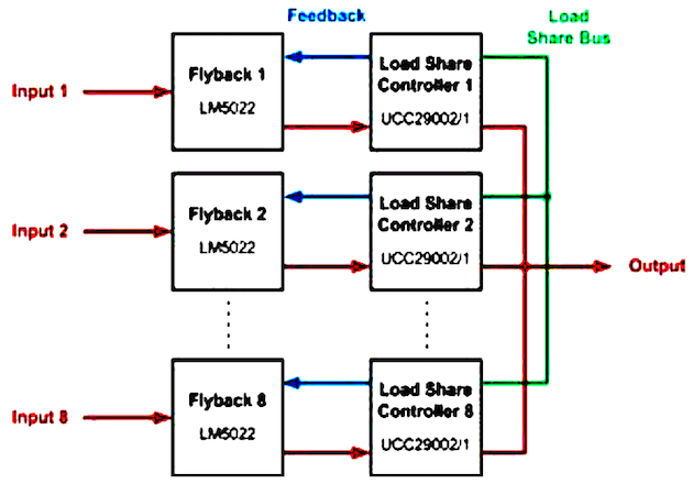
Figure 2: Block Diagram
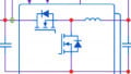
Implementation
Figure 2 shows the block diagram of the power supply solution. The flybacks are based on the LM5022 current-mode controller and provide the galvanic isolation between the inputs (end customer) and the load (DPU) using a standard PoE transformer from Würth (7491193912). On each output a UCC29002/1 load share controller takes care of equal sharing of the load between the converters.
This solution provides not only accurate load sharing but also increases the reliability of the system due to redundancy of the converters. The bandwidth of the load share controller is set to 200 Hz, which is about 1/10 of the bandwidth of the flyback. This ensures a slower response of the load sharing compared to the voltage regulation and prevents any interaction of the two loops.
Each converter has to provide only around 138 mA
If all eight converters are active and supply the maximum load of 1.1 A, each converter has to provide only around 138 mA. At a lower system load, this value becomes even smaller. According to this, the output current range of a single converter ranges from 1.1 A when only one converter is active down to several (tenth of) mA if all converters are active and only a low current is drawn.
This makes current measurement difficult as on the one hand the shunt should be as small as possible to keep the losses low at high load and only one or two active converters. On the other hand, at very low load and all converters active the current signal should be still large enough to ensure proper load sharing.
Accuracy of the load sharing is dependent on the shunt resistance and the load current
The accuracy of the load sharing is dependent on the shunt resistance and the load current as shown in Figure 3, Figure 4 and Figure 5. The output current variation of the eight converters was measured with different loads and shunts.
The measurements show clearly that a larger shunt and a higher load increases the accuracy of the current sharing which is understandable, because the measured signal becomes larger and the influence of noise and tolerances is reduced.
A shunt of 200 mΩ is a good trade-off between losses and accuracy for this application. At full load, the current variation is around ±5% and at 0.5A still within ±10%. For higher accuracy the shunt can be increased but this has to be paid with higher losses and therefore lower efficiency.
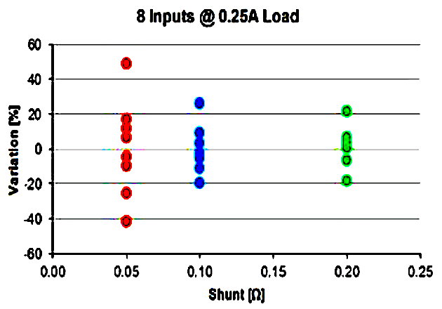
Figure 3: Current Variation @ 0.25A Load
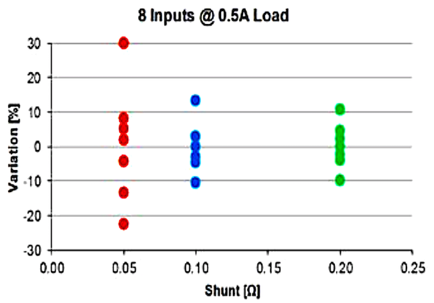
Figure 4: Current Variation @ 0.5A Load
Figure 6 shows the efficiency of a single converter, peaking close to 90%.
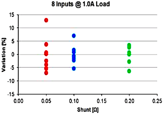
Figure 5: Current Variation @ 1.0A Load
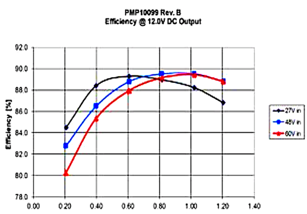
Figure 6: Efficiency of a single converter
The size of the reverse power solution measures only 65 x 220 mm (Figure 7) with the components mainly populated on the top side.

Figure 7: Board Photo
Conclusion
To increase the speed of the internet access for end customers from VDSL2 to G.fast, the infrastructure needs to be changed. To keep the constructional work at a minimum, the DPU is powered by the end customers and not by the power grid anymore. This gives a higher freedom of positioning the new DPU as no power lines need to be laid or moved. The DPU comes closer to the end customer which reduces the length of the loop and thereby results in higher data rates up to 1 Gbit/s. Powering the DPU by the end customer is done by Reverse Power Feed, which is an integral part of the FTTdp topology.
This article shows a built and tested reverse power feed solution for eight participants which provide a common output to supply the electronic of the DPU. It provides a galvanic isolation between the inputs and the output and an accurate load sharing to ensure a fair and equal distribution of the load between all active participants. It is a robust solution providing also redundancy as a single converter is capable to provide the maximum specified power.
The load sharing circuit can be modified easily to provide higher output power to support for example also 21VA, which is the maximum power for the short range reverse power feed class specification. Further information including schematic, layout, bill of material and test report is available in TI’s reference design library for power management (www.ti.com/powerlab-eu) with PMP10099 as reference.
About the author
Matthias Ulmann was born in Ulm, Germany, in 1980. He was awarded a degree in electrical engineering from the University of Ulm in 2006. After working for several years in the field of motor control and solar inverters (specialized in IGBT-drivers), he joined TIs’ Analog Academy for a one year trainee program. Since 2010 he has worked in the EMEA Design Services Group as a Reference Design Engineer in Freising, Germany. His design activity includes isolated and nonisolated DC/DC converters for all application segments.
References
Related Content