Facebook
 Google
 GitHub
 Linkedin
Rethinking Inductor Sizing: The High-Gain Magnetic Illusion
By defining a Utilization Factor, this article debunks inductor sizing myths and presents a strategic framework for magnetic volume optimization in high-gain DC-DC converters.
This article is published by EEPower as part of an exclusive digital content partnership with Bodo’s Power Systems.
Two common design intuitions frequently mislead engineers when selecting inductors for DC-DC converters: first, that inductor size scales linearly with processed power; and second, that cascading Boost stages improves magnetic utilization in high-gain applications. By defining a formal Utilization Factor (UF) metric and anchoring it against physical core data, this article debunks both myths. We demonstrate why high-gain Boost topologies are inherently poor magnetic utilizers and offer a strategic architectural framework for volume optimization.
Physical Law: Size Follows Energy, Not Power
A persistent industry misconception assumes that a power increase of X translates to a magnetic volume increase of X, or that multiplying the input voltage enables proportional power processing through the same core.

Image used courtesy of Freepik
From first principles, the physical volume (Ve) of an inductor is bound by its maximum magnetic energy handling capability:
\[E=\frac{1}{2}*L*I^{2}\]
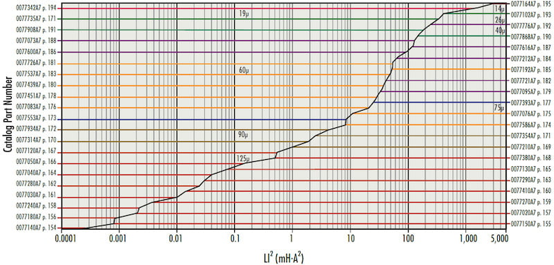
Figure 1. Magnetics' Kool Mµ catalog data: Core volume vs. energy handling capacity (L·I2). Image used courtesy of Bodo’s Power Systems [PDF]
Let’s extract the volume from the vertical axis, using the datasheet.
| P/N | LI2 [J] | Ve [mm3] | a=Ve/LI2 |
| 0077140A7 | 0.0002 | 10.5 | 52500 |
| 0077240A7 | 0.0022 | 64.9 | 29500 |
| 0077280A7 | 0.025 | 164 | 6560 |
| 0077050A7 | 0.15 | 340 | 2267 |
| 0077314A7 | 1.8 | 1800 | 1000 |
| 0077553A7 | 8.5 | 5,340 | 628 |
| 0077451A7 | 28 | 15,100 | 539 |
| 0077537A7 | 50 | 22,000 | 440 |
| 0077600A7 | 90 | 33,900 | 377 |
| 0077908A7 | 180 | 43,400 | 241 |
| 0077342A7 | 1500 | 220,000 | 147 |
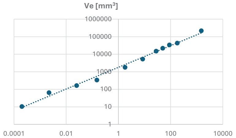
Image used courtesy of Bodo’s Power Systems [PDF]
A log-log fit of this data yields an exceptionally tight slope of 0.97 (R2 = 0.99), rigorously proving a linear physical law. For medium-to-large 60µ cores, a reliable volumetric design baseline is established at: Ve ≈ 300 · E [mm3/mJ]
Note: While this analysis explicitly tracks core volume (Ve), total winding volume scales proportionately under equivalent restrictions imposed by core saturation (Bmax):
\[E=\frac{1}{2}\cdot L\cdot Imax^{2}\propto\cdot Ae\cdot le\cdot Bmax^{2}\propto Ve\]
Empirical Catalog Validation
To bridge the gap between textbook physics and hardware realities, physical volume (Ve) and energy handling capacity (LI2) data were mapped across four decades of core sizes from Magnetics’ Kool Mµ toroid catalog.
We can clearly see that the manufacturer uses the Energy to be handled (X-axis) as the prime factor for selecting a core.
A log-log fit of this data yields an exceptionally tight slope of 0.62 (R2 = 0.99), demonstrating a clear scaling law. For medium-to-large 60 µm cores, a reliable volumetric design baseline is established at: Ve ≈ 300 · E [mm³/mJ]
Note: While this analysis explicitly tracks core volume (Ve), total winding volume scales proportionately under equivalent copper loss limits, preserving the same law’s system-level validity.
Defining the Utilization Factor (UF)
To evaluate how effectively a topology utilizes its magnetic volume, we define the Utilization Factor (UF) as the ratio of average power processed to peak stored energy:
\[UF\triangleq\frac{P}{E}\left[\frac{W}{J}\right]\]
By maintaining a fixed proportional peak-to-peak ripple current ratio (k = ∆I / (I) ≤ 0.1) under continuous conduction mode (CCM), closed-form UF expressions can be derived across various topologies:
Single-Ended (SE) Boost vs. Dual Floating Outputs (DFO) Boost
In a standard single-ended (SE) Boost converter, mapping duty cycle (D) to the voltage conversion ratio (M = Vo / Vin) yields:
\[UF_{Boost}\approx\frac{2\cdot k\cdot F_{S}}{D}\approx 2\cdot k\cdot F_{S}\cdot\frac{M}{(M-1)}\]
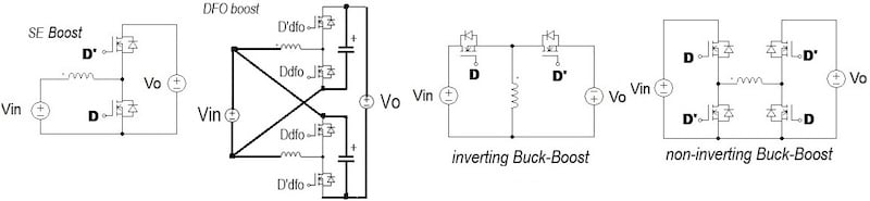
Figure 2. Evaluated non-isolated converter topologies. Image used courtesy of Bodo’s Power Systems [PDF]
Engineers often hope that alternative topologies like the Dual Flying Outputs (DFO) Boost can shrink magnetics due to a lower operating duty cycle. However, because DFO-Boost has a lower duty ratio compared to SE Boost for the same operational conditions, we must write the UF as a function of the conversion ratio M to perform an accurate comparison.
An energy-balance derivation reveals that for two equal, uncoupled inductors:
\[UF_{DFO}\approx2\cdot k\cdot F_{S}\cdot\frac{M}{M-1}\]
Conclusion: The total magnetic volume of a DFO Boost exactly equals its single-ended counterpart (UFSE = UFDFO); splitting the phase provides zero volumetric advantage for the core.
Buck and Buck-Boost Topologies
Applying the identical framework to Buck and Buck-Boost circuits highlights completely different magnetic behaviors:
- Buck: \(UF_{Buck}\approx 2\cdot k\cdot F_{S}\cdot\frac{1}{1-M}\) (As M → 1, UF → ∞ , meaning magnetic utilization becomes highly efficient near unity conversion).
- Buck-Boost: \(UF_{BB}\approx \frac{2\cdot k\cdot F_{S}}{1+k}\approx2\cdot k\cdot F_{S}\) (The metric is perfectly flat – utilization remains strictly independent of the voltage ratio M).
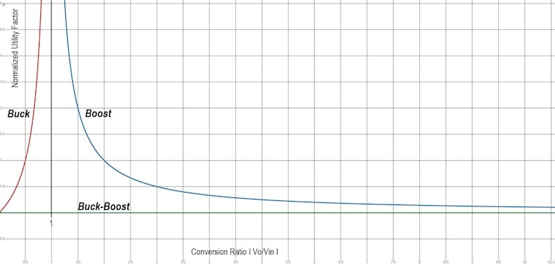
Figure 3. Normalized Utilization Factor (UF) vs. conversion ratio (Vo/Vin). Image used courtesy of Bodo’s Power Systems [PDF]
The High-Gain Illusion
The UF curve for a Boost converter reveals an alarming structural trap: beyond a conversion ratio of M = 5, the utilization factor rapidly plateaus near its floor (≈ 2k Fs)
Faced with a high-gain requirement (e.g., 10V → 400V, Mtot = 40), a common instinct is to cascade multiple stages (m = 3) under the assumption that smaller per-stage gains
(m =\(M^{1/n}_{tot}\)= 3.42) will relieve magnetic stress.
The Mathematical Penalty of Cascading
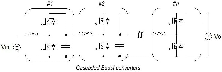
Figure 4. Multi-stage cascaded Boost converter architecture. Image used courtesy of Bodo’s Power Systems [PDF]
For n cascaded lossless Boost stages processing equal power (P), total stored energy is the sum of individual stage requirements:
\[E_{tot}=\sum^{n}_{i=1}\frac{P}{UF_{i}}\propto\sum^{n}_{i=1}\frac{M_{i}-1}{M_{i}}\]
By substituting xi = ln Mi, the objective function turns into maximizing ∑e-xi under a strict sum constraint (∑xi = lnMtot). Because f(x) = e-x is strictly convex, Jensen’s Inequality dictates that the minimum total energy state occurs only when all stages share an identical gain split
(Mi = \(M^{1/n}_{tot}\)). At this mathematically optimal split, the system-level utilization factor becomes:
\[UF_{tot}=\frac{UFstage}{n}\]
This proof uncovers a harsh reality: while cascading lowers the per-stage gain and only slightly ticks up individual stage UFs, dividing the entire system efficiency by n mathematically dominates. Consequently, adding stages always forces a total stored energy penalty.
Case Study: 10V → 400V (100W, 100kHz , k = 0.1)
- Single Stage (n = 1 , M = 40): Processes the power with a total magnetic energy storage of 5.36 mJ
- Three Stages (n = 3 , optimal m = 3.42): Each stage stores an identical 3.89 mJ , culminating in a total system energy requirement of 11.68 mJ
Cascading tripled the number of components while more than doubling the total physical volume and cost of the magnetics
(11.68 mJ vs 5.36 mJ)!
PSIM simulation circuits (below) and their corresponding waveforms shown below validate this analysis.
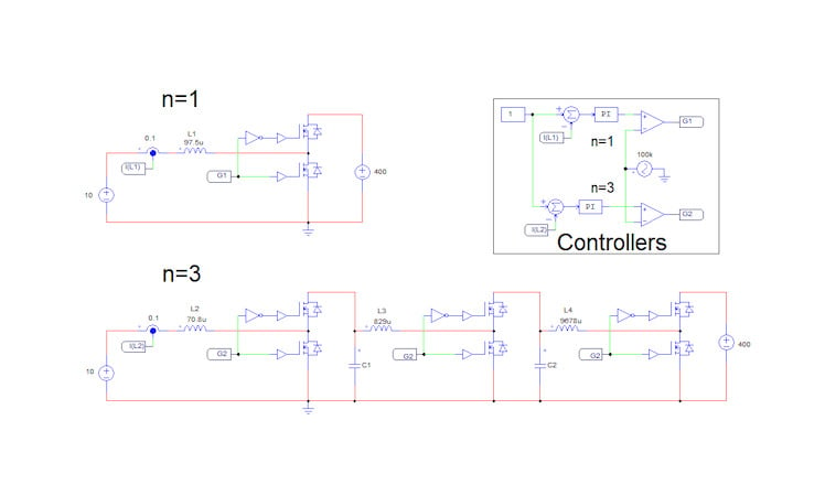
Figure 5. PSIM simulation schematics (n = 1 vs. n = 3). Image used courtesy of Bodo’s Power Systems [PDF]
Sizing Conclusions & Practical Takeaways
When a converter operates in the “flat zone” (M » 5), attempting to force a Boost architecture – whether single-stage or cascaded – is fundamentally flawed for magnetic volume optimization. Cascading should only be chosen to resolve switch voltage stress or component limitations, never to optimize core size.
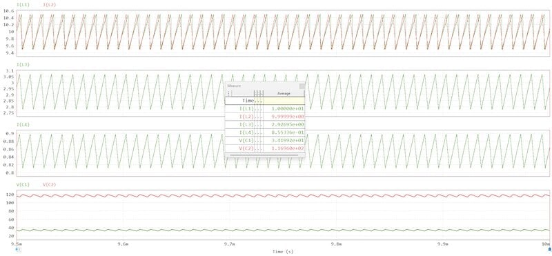
Figure 6. PSIM simulation waveforms validating currents and stored energy. Image used courtesy of Bodo’s Power Systems [PDF]
The Engineering Solution: For high-gain conversion, implement a decoupled two-stage architecture:
1. First Stage: A non-isolated converter (e.g., Buck-Boost or moderate Boost) operating at a highly favorable, low conversion ratio (M < 3) to step up to an intermediate rail.
2. Second Stage: A transformer-based isolated topology (such as an LLC or Phase-Shifted Full Bridge) to efficiently absorb the heavy high-gain requirements via turns-ratio scaling rather than massive inductive energy storage.
By keeping both stages firmly inside their magnetically efficient zones, total inductor volume is minimized. This framework was validated in practice, where the proposed topological shift successfully drove a substantial reduction in physical hardware size.
This article originally appeared in Bodo’s Power Systems [PDF] magazine.
Related Content