Facebook
 Google
 GitHub
 Linkedin
Next Generation Power Module Simulation Environment
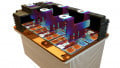
Design challenges for power modules can be solved by simulation. However, when there are multiple modules, topologies and components involved, is it possible to simulate it in an accurate and fast way? How does one really know, how a power module behaves in a real application? Vincotech took on the challenge and now introduces the simulation environment, VINcoSIM.
In Vincotech’s power module product portfolio one half consists of standard modules available for everyone. However, the other half is customized, which can mean a small change in an existing product, or even a complete new topology with semiconductor components coming from other various suppliers. Choosing the best-fitting properties of components and putting these together ensure a high-efficient and stable operation. But the rapidly increasing number of modules, topologies and components puts the challenge on the table when it comes to simulation. In addition, there are side effects such as switching and conduction loss and junction temperature swing, which have a strong effect on the performance. Can simulation results be trusted? With nearly 20 years of experience and help of digitization Vincotech introduces a completely new support solution, VINcoSIM, a new user-friendly simulation tool. Utilizing the new environment, every Vincotech power module, independently from the sub-topology or the components inside in it, can be tested and evaluated fast and accurately. Simply said, VINcoSIM improves power module design process and helps to make the best business decisions.
Product Modeling
One major basis of the VINcoSIM simulation environment is the model creation of power modules. This can be separated into multiple steps which describe how the sub-topologies have to be simulated and how the characteristics of an existing product are connected to the sub-topologies.
From a theoretical point of view the most important part is how the sub-topologies can be modelled, which is not obvious at the first glance. A general theory, which can simulate all available topologies and products in Vincotech portfolio, had to be created. It also has to be future-proofed.
Power modules can be built up using different kind of sub-topologies. Depending on the target application and the power-conversion stages, the sub-topologies can be split into multiple logical elements. These elements are introduced as functional topologies, which are the smallest technical and theoretical units. With combinations of these functional topologies different kind of solutions can be constructed in which each unit has its own tasks and can be described with one model.
The next step is creating a simulation model with functional topologies. A topology-independent representation has to be defined so that any kind of power conversion or topology can be described.
The method is based on how a simulated position in a functional topology operates at a certain section of a time period. Therefore, this kind of description is independent from the number of simulated positions and the modelling is suitable for both periodic and constant signals. This means bi-directional DC-AC or DC-DC conversions can be described. For periodic signals the frequency of the signal determines the period, and for constant signals a time window for simulation has to be defined.
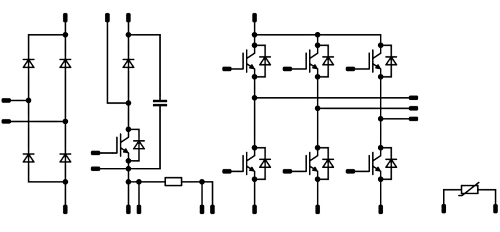
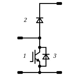
Simulated functional positions:
1 – DC Switch L
2 – DC Diode H
3 – DC Diode L
Figure 1. Example of how to divide the sub-topology to functional topologies and then one functional topology into functional positions. Image used courtesy of Bodo’s Power Systems
The second assumption is that the switching pulses are averaged in one period and therefore no exact switching phenomena is simulated. With this a high frequency switching will be taken into account only later in the switching loss calculation. Low frequency, 50 Hz or 60 Hz, switching is defining only the direction of the conduction.
For each and every functional topology the following technical information is needed in order to have a working model:
• Input parameters for simulation
• Operation modes e.g. inverter, rectifier, PFC
• Modulation methods e.g. SPWM, THIPWM
• Operation mode and modulation method dependent on excitation current and voltage waveform equations
• Operation mode and modulation method dependent on duty cycle equation
• Loss calculation table
• Component types in functional topology positions
This way of modelling ensures that if new topologies or operation modes and modulation methods need to be integrated, it can be performed fast and easily. The provided equations are the excitation waveforms for the simulation with which the loss calculation can be executed.
In order to have a description for topology-independent loss calculation, a loss calculation table is introduced. When the simulated functional topology positions are defined (e.g. AC Switch High Side and AC Diode High Side for a 2-level inverter), the behavior has to be described. With the background solution, dependently from the number of components or from the modulation method, the same structure can be used for the description. The general loss calculation description for semiconductor devices comes here in the picture.
| Operation mode | Modulation method | Exc. Waveforms | Duty cycle function | Loss calculation | Positions |
| Inverter | SPWM |
Iin, Uin Iout, Uout |
D(t) | Inverter loss calculation table |
• AC Switch H • AC Diode H • AC Switch L • AC Diode L |
| THIPWM |
Iin, Uin Iout, Uout |
D(t) | Inverter loss calculation table | ||
| Buck | CCM |
Iin, Uin Iout, Uout |
D(t) | Buck loss calculation table | |
| Boost | CCM |
Iin, Uin Iout, Uout |
D(t) | Boost loss calculation table |
Table 1. Example of functional topology model content for a 2-level inverter.
First, the number of positions has to be identified followed by the applicable operation modes and modulation methods. Then, using the previously-mentioned excitation waveforms, for every position there has to be a description how they are working at a given time segment. The basis of the period is the output frequency, or input frequency in case of inverter type topologies. For converters 20ms is specified as a basic period. The basic period is split into multiple operation periods based on the voltage and current directions. For example in a general 2-level inverter four operation periods can be identified based on how voltage and current signs relate to each other - i.e. how the topology can ensure the current flow in different directions based on the sign of the voltage.
In every section it has to be described how the simulated position is operating. It has to be identified if only conduction or switching phenomenon occurs. In case of conduction the position will get besides the excitation waveforms the defined duty cycle segment as static, thermal and dynamic, which verify the proper operation of the module.
Every component is measured during power module characterization, the precondition of which is to have qualified mechanical and electronical components inside it as well as to pass the end of manufacturing test. Details about the measurement setup and configuration can be found in Vincotech’s „Power module datasheet explanation” which can be downloaded from Vincotech website. The characterization consists of static and thermal measurements for individual components and dynamic measurement for commutation loops to have transient behavior information.
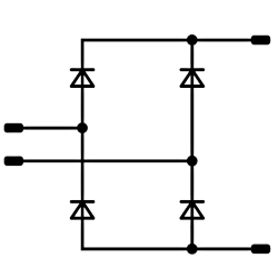
For the usage of characteristics a generalized structure needs to be defined, which is independent from the type of measurement and component. Therefore the Vincotech Electric Block (VEB), which is a virtual characteristic model derived from real measurements, is introduced. These VEBs are differentiated by their types: VSB is Vincotech Static Block, VDB is Vincotech Dynamic Block and VTB is the Vincotech Thermal Block. This kind of modelling provides flexibility to reuse the blocks for other purposes such as concept creation or validation.
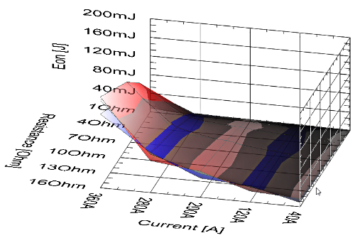
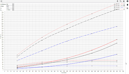
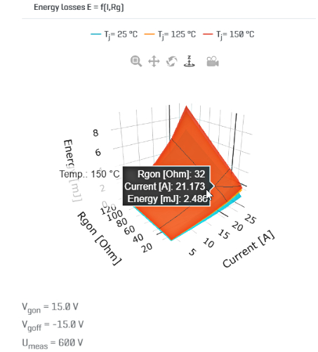
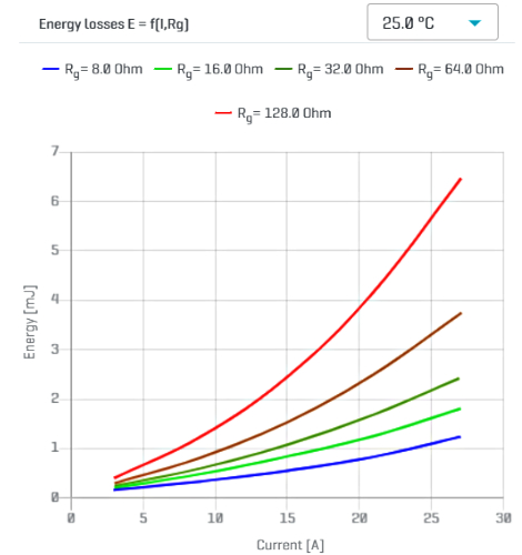
Figure 2. Example of a Vincotech Dynamic Block (VDB) during evaluation and in VINcoSIM. Image used courtesy of Bodo’s Power Systems
With the help of digitalization all the VEBs are stored in a database and the source can be traced back to measurement parameter and configuration level. In addition the raw, measured physical signals can be reached easily. This centralized characterization database ensures that the data can be accessed fast and the content is reliable and validated.
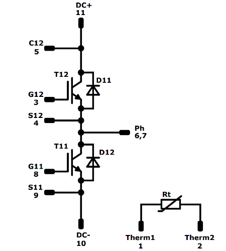
The sub-topologies have reference designators, which identify the semiconductors of the power module. These designators can be mapped, based on the functional topology modelling presented before, with simulatable positions. In each functional topology, depending on the operation mode or modulation method, it is defined what kind of characteristics are needed to execute simulation. For example, for those positions, which are conducting, only static and thermal blocks are needed, but for those ones, which perform switching action, a dynamic block is required as well. At this point the VSB, VTB and VDB have to be linked to the reference designator, which was measured in the given product.
The result is that a complete product has a BoM list, where the components and their reference designators are connected to simulation positions in which the defined characteristics blocks will take place. It has to be noted that, thanks to this approach, MOSFET based modules can be easily simulated, taking into consideration the channel and body diode behavior as-well as separated simulatable positions.
In this generalized modelling way, on topology and product level, a rework of a complete module is flexible or new product models can be released fast.
As a summary the following information is needed to describe a product:
| Product level | Simulation model level | Characteristics level |
| T11 | AC Switch L | VSB 1, VTB 1, VDB 1 |
| T12 | AC Switch H | VSB 1, VTB 1, VDB 2 |
| D11 | AC Diode H | VSB 2, VTB 2, VDB 1 |
| D12 | AC Diode L | VSB 2, VTB 2, VDB 2 |
Table 2. An example of a product-topology-characteristics mapping.
| Product level | Sub-Topology level | Functional topology level |
|
• Sub-topology type • Semiconductors and their types • Static characteristics • Thermal characteristics • Dynamic characteristics |
• Number and type of functional topologies |
• Application parameters • Operation modes • Modulation methods • Operation mode and modulation method dependent on excitation current and voltage waveform • Operation mode and modulation method dependent on duty cycle function • Loss calculation table • Component types in functional topology positions |
Simulation Process
For loss calculation the simulation software uses a temperaturefeedback calculation and simulates the temperature dependent on the loss time function for each semiconductor device in the power module.
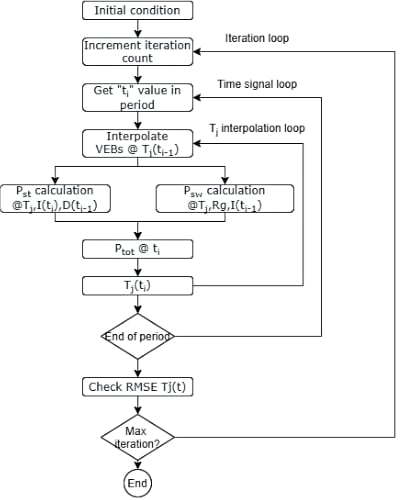
Figure 3. The simulation workflow of the VINcoSIM engine. Image used courtesy of Bodo’s Power Systems
The basis is a topology model, which describes in the given topology how the semiconductor device positions are working and when within the period. For one period the logic steps through defined excitation current and voltage waveforms point-by-point and calculates the losses and the temperature.
The initial condition of the simulation is an average loss and temperature calculation using the 125 °C or 150 °C static and dynamic characteristics. The result is an average junction temperature. This is the initialization point for the main calculation, which means the existing semiconductor characteristics are interpolated using this temperature value, and the calculation of the next excitation waveform point is performed on this characteristics. This is executed until the end of the period. At the end of the period an RMS Error is calculated (Eq. 1), which determines the number of iterations. The initial condition of the simulation is an average loss and temperature calculation using the 125 °C or 150 °C static and dynamic characteristics.
\[T_{j}(t)RMSE= \frac{RMS(T_{i-1}(t)-T_{i}(t))}{RMS(T_{i-1}(t))}\]
The main logic of the simulation is the temperature feedback for which the simulator uses a basic differential equation and solving it with Euler formula.
\[\frac{\Delta T_{m}(t)}{dt}=\frac{[(P(t,T)*R_{m})-\Delta T_{m_{i-1}}(t)}{\tau_{m}}\]
If the power module has multiple phases or legs, the model separates them in the background. If the semiconductor device is phaseshifted, then the loss values are copied and shifted with phase shift time from the base position. The phase shift time is defined in the topology model. If the custom-heatsink is defined, the engine takes into account the thermal transient impedance of the defined heatsink and calculates the heatsink temperature as well as the junction temperature accordingly.
Design Examples
A chosen power module is for a single-phase 6 kW PV application, and the target switching frequency is 32 kHz. The newly developed H6.5 topology is considered, as this has a high efficiency. Finally a 50 A device is selected and the loss and junction temperatures are required to stay below 140 W and 125 °C at a maximum heatsink temperature of 80 °C. The following figure shows how the module behaves with the mentioned operation conditions.
The simulation results show a total module loss of 115 W and a maximum junction temperature of 124 °C. Thus the chosen module fits well in the requirements.
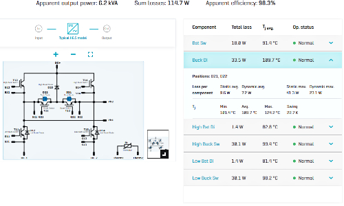
Figure 4. Simulation results of a H6.5 topology. Image used courtesy of Bodo’s Power Systems
Benefits and summary
The new simulation software, VINcoSIM shows accurate and fast calculations. It is not limited to standard topologies and integration of new simulation models is quite easy. With its capability to use different simulation methods it is well-prepared for the future. The differentiation from a topology to sub-topologies and finally to virtual elements with no restrictions enables it to build up nonexisting power modules in the future and simulate these under various kind of conditions.
If you want to know more, please join us in a webinar Oct 4th!
This article originally appeared in Bodo’s Power Systems magazine.