Facebook
 Google
 GitHub
 Linkedin
NEC Basics: Impedance-Grounded Systems and Equipment Grounding Above 1 kV
Learn about limiting the available ground-fault current and how to ground equipment above 1 kV.
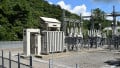
The energy discharged at a fault location is roughly proportional to the square of the fault current magnitude. The most common type of fault in commercial and industrial power systems is from a phase to the ground or ground fault. A method to reduce personnel hazards, damage to faulted equipment, and fire possibility is to limit the available ground-fault current by inserting an impedance in the circuit from neutral to the ground.

Image used courtesy of Pixabay
National Electrical Code Section 250.187 Impedance-Grounded Systems
The impedance-grounded systems insert an impedance—resistance or reactance—between the neutral point and the earth, limiting the ground-fault currents to values that will not excessively damage circuits and equipment.

Image used courtesy of Adobe Stock
Resistance grounding is preferred in industrial power systems to ensure reduced magnitudes of ground-fault current—this is critical primarily for ground faults in the windings of generators and motors. This section of the NEC confirms that the typical impedance device is the resistor.
Meet the following conditions to employ impedance-grounded systems to limit the ground-fault current:
- Make sure that only qualified persons service the installation.
- Install ground detectors.
- Do not serve line-to-neutral loads.
In addition, the impedance-grounded system must follow sections 250.187(A) through (D).
Section 250.187(A) Location
- Install the grounding impedance device between the impedance grounding conductor and the grounding electrode conductor.
Section 250.187(B) Insulated
- Insulate the impedance grounding conductor for the maximum neutral voltage.
Exception: You may use a bare impedance grounding conductor if the uncovered portion of the conductor and the grounding impedance are not readily accessible and securely apart from the ungrounded conductors.
Section 250.187(C) Neutral Point Connection
- Connect the system’s neutral point to the ground only through the grounding impedance device.
Section 250.187(D) Equipment Grounding Conductors
- Connect the equipment grounding conductors to the ground bus and grounding electrode conductor. It is permitted to employ bare equipment grounding conductors.
Figure 1 shows a Y-connected system—with a neutral point available—grounded through an impedance. This arrangement complies with sections 250.187(A) through (D).

Figure 1. An impedance-grounded system. Image used courtesy of Lorenzo Mari
National Electrical Code Section 250.188 Grounding of Systems Supplying Portable or Mobile Equipment
According to NEC’s Article 100 “Definitions,” portable equipment is easily moved between places in regular use, and portable substations are assemblies, typically on trailers, containing transformers and switchgear.
Mobile equipment may be described as effortlessly moving on treads, wheels, etc.
Large portable equipment, like electric shovels and similar machines, usually receive power through high-voltage flexible trailing cable—typical voltages are 2 400 V and 4 160 V. The safety of operators and helpers obliges designers and builders of electric supply systems to take protective measures against ground-fault currents and lightning.
This section requires systems supplying portable or mobile equipment over 1 kV, other than temporary substations, to comply with sections 250.188(A) through (F).
Section 250.188(A) Portable or Mobile Equipment
- Feed portable or mobile equipment over 1 kV from an impedance-grounded system.
- Derive a system neutral in delta-connected supplies.
Section 250.188(B) Exposed Non-Current-Carrying Metal Parts
- Connect all exposed non-current-carrying metal parts to the grounding point of the system impedance device utilizing an equipment grounding conductor.
Section 250.188(C) Ground-Fault Current
- Do not exceed 100 V—generated by the maximum ground-fault current available—between the portable or mobile equipment frame and the ground.
Select the substation grounding resistor to keep the maximum equipment frame potential to 100 V or less under ground-fault conditions.
Section 250.188(D) Ground-Fault Detection and Relaying
- Provide ground-fault and relaying systems to de-energize any high-voltage component with a fault-to-ground.
- Monitor the connection of the equipment grounding conductor and de-energize the high-voltage feeder upon loss of continuity.
Section 250.188(E) Isolation
- Isolate from and separate the grounding electrode at least 6 m from any other system or equipment grounding electrode.
- Do not connect directly the grounding electrodes with elements like buried pipes, fences, etc.
The ground-fault current originating in the high-voltage supply system may be significant. A high ground-fault current flowing through the grounding grid at the primary substation will cause the entire structure to elevate its potential for several kilovolts above the ground. This potential will remain until the high-voltage-system protective device operates – which may take several cycles.
Suppose the protective ground of the portable or mobile equipment is physically interconnected with the main substation ground. In that case, the high potential will be transferred to the equipment’s frame, creating a critical hazard.
Due to the previous facts, the recommendation is to keep the grounding electrode isolated from the main substation ground system and any other system or equipment grounding electrode.
The voltage gradient on the earth surrounding the main substation swiftly lessens as we walk away from it. A minimum separation of 6 m between the two grounding systems is sufficient to avoid any substantial coupling.
It is essential to avoid the interconnection between the two grounding systems that buried pipes, fences, and the like may create.
Section 250.188(F) Trailing Cable and Couplers
- Comply with the requirements of Part III of Article 400 for cables and Article 495.65 for couplers.
Figure 2 shows an electric shovel receiving power from a high-voltage impedance-grounded system that complies with sections 250.188(A) through (F).

Figure 2. A portable machine fed from an impedance-grounded system. Image used courtesy of Lorenzo Mari
National Electrical Code Section 250.190 Grounding of Equipment
Section 250.190(A) Equipment Grounding
- Ground all non-current-carrying metal parts of fixed, portable, and mobile equipment.
- Ground the associated fences, enclosures, housings, and supporting structures.
Exception: There is no need to ground the metal parts if they are isolated from the ground and placed so that a person cannot simultaneously be in contact with the metal parts of energized equipment and the earth.
The Exception N° 2 to Section 250.110 states that distribution apparatus, such as transformers and capacitor cases, are not required to be grounded if mounted on wooden poles at a minimum height of 2.5 m above ground or grade level.
Section 250.190(B) Grounding Electrode Conductor
- If a grounding electrode conductor connects the non-current-carrying metal parts of equipment to the ground, size it per Table 250.66.
The smallest size of the grounding electrode conductor must be N° 6 AWG copper or N° 4 AWG aluminum or copper-clad aluminum.
Figure 3 shows the non-current-carrying parts of an electric motor grounded through a building’s steel column.

Figure 3. A motor frame grounded through a building column. Image used courtesy of Lorenzo Mari
Furthermore, an equipment grounding conductor must be run from the non-current-carrying parts of the motor to the ground bus in the electrical supply source.
The high reactance of the avenues provided through the building’s structure may not furnish an effective ground-fault current path—impeding the proper operation of the overcurrent protective devices or ground-fault detectors.
Section 250.190(C) Equipment Grounding Conductor
The equipment grounding conductor must comply with sections 250.190(C)(1) through (3).
250.190(C)(1) General
The minimum size of an equipment grounding conductor not integrated into a cable assembly must be N° 6 AWG copper or N° 4 AWG aluminum or copper-clad aluminum.
250.190(C)(2) Shielded Cables
- You may use the metallic insulation shield enclosing the current-carrying conductors as an equipment grounding conductor if rated for the clearing time of the ground-fault protective device—the ground-fault current must not damage the metallic shield.
- Do not employ the metallic tape insulation shield and drain wire insulation shield as equipment grounding conductors in solidly grounded systems.
The functions of a cable’s metallic shield or sheath are:
- Conduct charging, fault, or unbalanced current.
- Protect mechanically.
- Protect against induced voltage.
- Limit radio interference.
- Dissipate heat.
250.190(C)(3) Sizing
- Size the equipment grounding conductor per Table 250.122.
National Electrical Code Section 250.191 Grounding System at AC Substations
- Follow the rules of Part III of Article 250 for the grounding system of AC substations.
The Informational Note in this section recommends consulting the IEEE 80, “IEEE Guide to Safety in AC Substation Grounding,“ for additional material.
National Electrical Code Section 250.194 Grounding and Bonding of Fences and Other Metal Structures
- Ground and bond the metal fences enclosing a substation and other metal structures in or surrounding it if the substation has exposed electrical conductors and equipment. This practice limits step, touch, and transfer voltages.
Section 250.194(A) Metal Fences
- Bond the metal fence to the grounding electrode system with a wire-type bonding jumper if the fence is positioned within 5 m of the exposed electrical conductors or equipment.
Fence grounding deserves significant attention and detailed analysis since it is habitually accessible to people unrelated to the electrical facilities, making this issue a matter of the general public’s safety.
Fences may be exposed to adverse voltage potentials from several sources, such as falling electrical conductors, operation or failure in supply substations, objectionable currents, and lightning. The amount of exposure is particular to every site. The grounding requirement aims to limit the fences’ potential under such conditions.
This section lists six specific methods to ground the fence:
- Install bonding jumpers at fence corners and a maximum of 50 m intervals.
- Install bonding jumpers at both sides of overhead line crossings.
This connection contemplates a conductor falling, touch potentials, and induction at the crossing location.
- Bond the gates to the support posts. Bond each post to the grounding electrode system.
Experience shows that gate-hinging and gate-roller mechanisms do not conduct electricity effectively.
- Bond across gates or other openings employing a buried bonding jumper.
- Extend the grounding mat or electrode system to cover the gates’ swings.
- Bond the barbed wire strands to the grounding electrode system.
Alternate fence grounding designs are permitted if performed under engineering supervision. Diverse companies follow different practices.
The Informational Note N° 2 refers the user to IEEE 80, “IEEE Guide for Safety in AC Substation Grounding,” for directions in grounding fences in electric supply substations.
Section 250.194(B) Metal Structures
- Bond all unprotected metal structures, including guy wires, within 5m horizontally or 2.5 m vertically of exposed conductors or equipment to the grounding electrode system.
The bond and grounding electrode system must carry the current—in magnitude and duration—that may be imposed on them upon insulation failure, the falling of overhead HV conductors, or lightning discharges. The equipment grounding arrangement must sustain the thermal distress and prevent establishing dangerous voltages that may affect people in the surrounding area.
Takeaways of Impedance-Grounded Systems and Equipment Grounding Above 1 kV
- Impedance grounding consists of inserting an impedance between the impedance grounding conductor and the earth to limit the ground-fault current to safe limits.
- Ground-fault relays monitor ground-fault current, tripping the system overcurrent protective devices when needed.
- Large portable or mobile equipment is not located on fixed foundations, presenting significant difficulties for the safety of operators and aides under ground-fault conditions.
- Ground all non-current-carrying metal parts of fixed, portable, and mobile equipment and their associated fences, enclosures, housings, and supports.
- Ground and bond the metal fences and other metal structures in substations when in the presence of exposed electrical conductors.
For more on Lorenzo Mari’s NEC Basics series, please visit the following articles:
- NEC 2023 Basics: Grounding and Bonding Piping Systems and Exposed Structural Metal
- NEC 2023 Basics: Equipment Grounding Conductors
- NEC 2023 Basics: Identifying Wire-Type Equipment Grounding Conductors
- NEC 2023 Basics: Sizing Equipment Grounding Conductors
- NEC 2023 Basics: Equipment Grounding Conductor Continuity and Connections
- NEC Basics: Connections and Continuity of Equipment Grounding Conductors in Receptacles and Boxes
- NEC Basics: Grounding and Bonding DC Systems Supplying Premises
- NEC Basics: Solidly Grounded and Service-Supplied AC Systems Above 1 kV