Facebook
 Google
 GitHub
 Linkedin
NEC 2023 Basics: Identifying Wire-Type Equipment Grounding Conductors
This article will help you identify wire-type equipment grounding conductors.
National Electrical Code (NEC) Section 250.119 rules the identification of wire-type equipment grounding conductors, including a color code and alternatives for particular cases.

Image used courtesy of Pixabay
National Electrical Code Section 250.119 Identification of Wire-Type Equipment Grounding Conductors
Section 250.119(A) General
The basic rules are:
- Wire-type equipment grounding conductors may be bare, covered, or insulated unless required to be insulated elsewhere in the NEC.
- Individually covered or insulated conductors must have an uninterrupted surface colored green or green with one or more yellow stripes, with three exceptions.
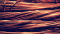
Figure 1 shows a conductor colored green with one continuous yellow stripe.

Figure 1. A conductor colored green with one continuous yellow stripe. Image used courtesy of Pixabay
The green color in Figure 2 qualifies to identify the conductor as equipment grounding.

Figure 2. A conductor identified as equipment grounding. Image used courtesy of Encore Wire
Do not use this color code to identify grounded or ungrounded conductors.
Note that the grounding electrode conductor is neither a grounded conductor nor an ungrounded conductor. Therefore, there is no restriction on using a grounding electrode conductor green or green with one or more yellow stripes.
Exception N° 1. Conductors for functions different from equipment grounding may use this color code in Class 2 or Class 3 power-limited circuits, power-limited fire alarm circuits or communications systems operating at less than 50 V AC or 60 V DC if connected to equipment not required to be grounded.
An example of this exception is a control circuit connected to the low-voltage side of a 120 V single-phase transformer. Note that the transformer’s low-voltage side must be grounded if the high-voltage side exceeds 150 V to the ground or is ungrounded, per Section 250.20(A). Exception 1 does not apply under these circumstances.
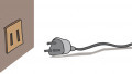
Exception N° 2. Flexible cords with integral insulation and jacket without an equipment grounding conductor may have a continuous green outer finish.
Examples of this exception are Christmas tree wires and extension cords. See Figures 3 and 4.

Figure 3. A Christmas tree wire. Image used courtesy of Pixabay

Figure 4. Green flexible cord SPT-2, 2-wire. Image used courtesy of Christmas-Leds
Exception N° 3. This exception permits using green insulation in ungrounded signal conductors installed between the output terminations of traffic signal control and traffic signal indicating heads.
The signaling circuits must include an equipment grounding conductor per Section 250.118. The equipment grounding conductor may be bare, insulated, or covered if wire-type. Insulated and covered conductors must obey the color code specified above.
This practice is typical in traffic signaling equipment.
Section 250.119(B) Conductors Size N° 4 AWG and Larger
These conductors must comply with the following rules:
- If the insulation does not comply with Section 250.119(A) during the installation process, identify the conductor permanently as an equipment grounding conductor at both ends and all accessible places.
Conductors may be of any color, and correct identification pertains.
Exception. There is no need to mark these conductor sizes in conduit bodies without splices or unemployed hubs.
- The identification methods permitted are:
◦ Removing the insulation or covering throughout the entire visible length.
The conductor will look bare by removing the insulation or covering along the exposed length.
◦ Coloring the insulation or covering ends in green.
◦ Marking the insulation or covering ends with green tape or green adhesive labels.
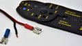
The identification method employed must encircle the conductor. See Figure 5.

Figure 5. Identification of conductors size N° 4 AWG and larger. Image used courtesy of Lorenzo Mari
Section 250.119(C) Multiconductor Cables
The term multiconductor designates wires or cables carrying more than one conductor, typically between two and twenty-five conductors – cables for specific purposes can surpass those figures.
A familiar application is for control uses – e.g., communications, remote signaling, and broadcasting.
Comply with the following rules:
- It is acceptable to permanently identify as equipment grounding conductor one or more insulated conductors, during the installation process, at both ends and at every point where the conductors are reachable.
As before, conductors may be of any color if appropriately identified.
- The identification methods permitted are similar to those for conductors size N° 4 AWG and larger – this time, however, the techniques apply regardless of size:
◦ Removing the insulation throughout the entire visible length.
◦ Coloring the visible insulation in green color.
◦ Marking the visible insulation with green tape or green adhesive labels.
The identification method employed must encircle the conductor.
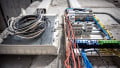
Figure 6 shows a multiconductor cable. One of the aforementioned permitted methods may identify one or more insulated conductors as equipment grounding conductors.

Figure 6. Multiconductor cable. Image used courtesy of Pixabay
Figure 7 shows three multiconductor cables, two with equipment grounding conductors identified with green color from the factory.

Figure 7. Multiconductor cables with green insulation from the factory. Image used courtesy of AutomationForum.co
Section 250.119(D) Flexible Cords
Equipment grounding conductors in flexible cords must comply with the following rules:
- Be insulated.
- Have a green or green with one or more yellow stripes continuous finish.
Figure 8 shows a flexible cord with an insulated equipment grounding conductor colored in green.

Figure 8. Equipment grounding conductor in a flexible cord. Image used courtesy of Southwire
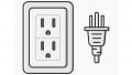
An extension cord is an example of a flexible cord. A 3-wire extension cord enables the grounding of any equipment connected to it.
Figure 9 shows an extension cord with ground. It incorporates a third wire and plug prong for grounding, taking three-pronged appliance cords.

Figure 9. Extension cord. Image used courtesy of F4P
Takeaways of Identifying Wire-Type Equipment Grounding Conductors
- Wire-type equipment grounding conductors may be bare, covered, or insulated.
- Green and green with one or more yellow stripes are restricted colors for the insulation or covering of equipment grounding conductors.
- Sections 250.119(B) and 250.119(C) permit using different colors in the conductor’s insulation or covering in particular cases and provide identification alternatives such as stripping, coloring, and marking.
To catch up on Lorenzo Mari’s series on National Electrical Code 2023 Basics: Grounding and Bonding, follow these links:
- National Electrical Code 2023 Basics: Equipment Grounding Conductors
- National Electrical Code 2023 Basics: Grounding and Bonding Part 18Grounding and Bonding Piping Systems and Exposed Structural Metal
Related Content