Facebook
 Google
 GitHub
 Linkedin
Magnetics Design Tool for Power Applications
This article discusses the features of the free app, SOFT Power, for simulations such as hysteresis modelling for reliable design of power applications.
Predicting the behavior of soft magnetic cores under realistic circuit application conditions allows making an optimum material and core selection. This requires visualizing material data of soft magnetic materials, as well as calculating core parameters such as inductance, core losses, transferable power and EMI suppression as well as associated basic winding design parameters.
The free app, Soft Power*, uses proven simulation methods such as hysteresis modeling for a reliable design, allowing faster time to market while maximizing engineering resources.
Material Parameters
Both soft ferrites and powder core materials are featured based on representative ring cores tested according to IEC Standards (IEC 60401-3, IEC 62044-1/2/3). The software shows graphs of relevant parameters for every material grade:
- Permeability µ vs. temperature, flux density and DC-Bias
- Complex permeability µ’, µ” vs. frequency
- Small-signal losses (tand/µ) vs. frequency
- Normalized impedance ZN vs. frequency
- Power losses Pv vs. frequency/flux density/temperature
- Hysteresis loops B(H)
Hysteresis Modeling
In order to accurately simulate high excitation parameters such as power loss and DC-bias at any given condition, hysteresis modeling is necessary. The use of models such as the Steinmetz power equation[1] have limited validity in the frequency, flux density and temperature ranges; extrapolating these limits can result in very large errors due to the exponential nature of the equation. The hysteresis models based on Hodgdon’s differential equation[2] naturally overcomes these limitations[3]. By regarding the measured major hysteresis loop as a particular solution to the equation, the upper and lower branches of a minor loop between the end points (Hm, Bm) and (HM, BM) can be described as a function of the upper and lower curves of the major loop:
With
and the commutation curve (4)
Where Hc is the coercivity, µc its permeability and Bs the saturation flux density. In addition to these parameters the model requires the knowledge of the initial permeability µi, which is also a well-defined quantity.
The measured major loop curves can be parametrized by the following heuristic description introducing the squareness exponents aL and aU for the lower and upper curves respectively: (5a) (5b)
Figure 1 shows one example of a major loop and a calculated minor loop.
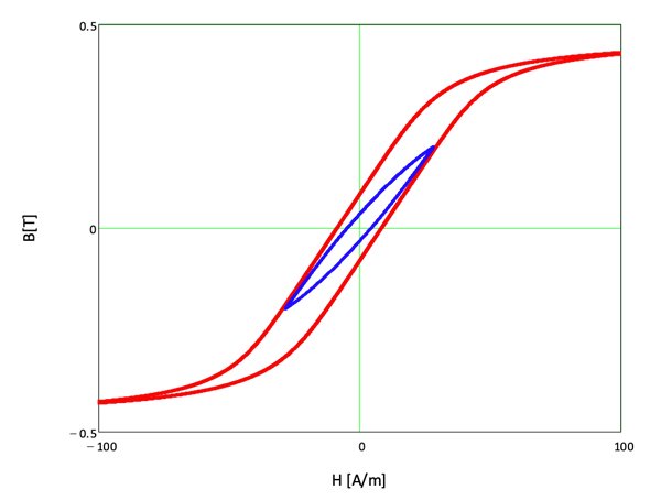
Fig. 1: Major loop for material DMR47 at 80°C. The symmetric minor loop was calculated for -Bm = BM = 200 mT
Derived Parameters
The calculation of application relevant quantities is straight forward:
Power Loss: the enclosed area of a symmetric minor loop of amplitude BM is obtained by integration:
Based on this and considering the frequency dependence, both power losses and the transferable power for a given core and winding can be calculated (Fig. 2a).
DC-bias: the reversible permeability µrev is given by the following expression:
.jpg)
The dc bias inductance is calculated from µrev and the dc-bias current Idc from the dc flux density Bdc (Fig. 3).
Temperature Dependence
The hysteresis parameters are determined for major loops tested at different temperatures. In order to allow the software to calculate related quantities at a given temperature, the five hysteresis model parameters are fitted as a function of temperature.
Core and Winding Parameters
Every core type is characterized by three geometrical parameters according to IEC 60205:
- le: effective magnetic length
- Ae: effective cross-sectional area
- Amin: smallest cross-section
In addition to this, a typical one-chamber bobbin is described by:
- lN: mean turn path
- AN: winding area
Based on these parameters it is possible to calculate transformer and inductor parameters for a given choice of core shape and material grade. Especially the frequency increase of the winding resistance (ACR/DCR) depends on its arrangement in the bobbin and the core surrounding it through the skin and proximity effects depending on both the number of turns and layers [4] (Fig. 2b).
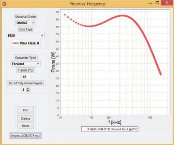
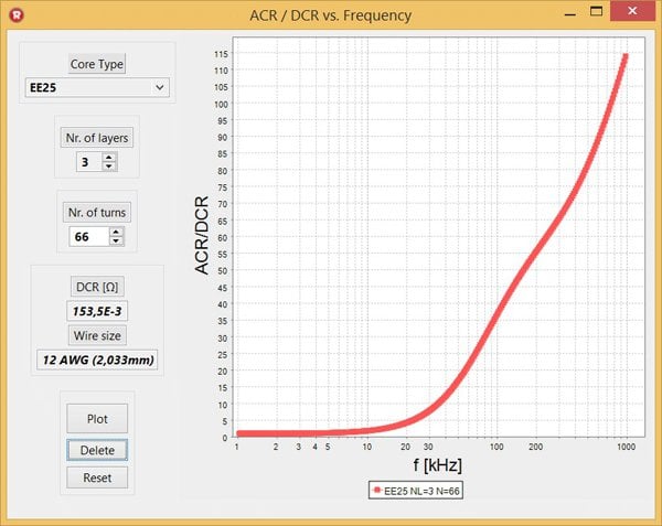
Fig. 2: (a) Transferable power for EE25 core in material DMR47 used in a forward converter topology at an ambient temperature of Tamb=40°C. (b) Corresponding ACR/DCR vs. frequency for the winding with three full wound layers and N=66 turns (AWG 12).
But also the winding capacitance is an important consideration for the high frequency behavior of e.g. an EMC filter inductor [5]. The program calculates it so as to provide the effect of the number of turns on the height and position of the impedance vs. frequency curve. This allows for example to fine tune the inductor design to mitigate electromagnetic interference (EMI) in switch-mode power supplies (Fig. 4).
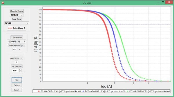
Fig. 3: Inductance vs. dc bias current for a choke built with an EC34A (ETD34) core with an air gap of g=1mm and N=100 turns in materials DMR40, DMR47 and DMR28 at T=25°C.
The effect of larger air gaps on the inductance needs to consider the fringing flux effect [6]. The software considers this in order to accurately calculate the inductance as a function of temperature and DC-bias.
The free-air convection thermal resistance of a wound component depends from the core volume and is needed to calculate the temperature increase in a power transformer. This is needed to calculate the transferable power (Fig. 2a).
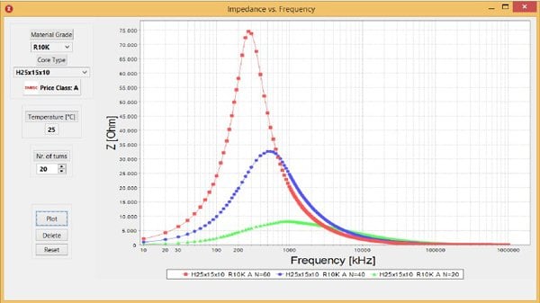
Fig. 4: Impedance vs. frequency for a toroid H25x15x10 in material R10K wound with N=20, 40 and 60 turns. Due to the winding capacitance which increases with the number of turns, the frequency of the impedance maximum decreases.
Material Menus
The front page provides an overview of material grades (MnZn ferrites, NiZn ferrites, powder core materials) core shapes and reference cost. With the help of these tables the user makes then a selection of materials to compare its properties to one another in the following menus:
- Permeability vs. Temperature: from -60°C up to Curie temperature
- Complex Permeability vs. Frequency: from 10 kHz up to 1 GHz. User can select between serial or parallel, real and imaginary permeability as well as normalized impedance.
- Incremental Permeability vs. Magnetic Field: up to saturation between 25°C and 140°C.
- Hysteresis Loop B(H): up to saturation between 25°C and 140°C.
- Amplitude Permeability vs. Flux Density: up to saturation between 25°C and 140°C
- Power Loss vs. Temperature/Frequency/Flux Density: displays losses as a function of temperature (between 25°C and 140°C), flux density (up to saturation) or frequency (from 10 kHz up to 3.5 MHz) with the two other parameters fixed.
Core Menus
Once the user has selected the material grade for his application, he can then select a suitable core shape and calculate for it the following parameters related to his application:
- Gapped AL | µe vs. Temperature: calculation of AL-value including fringing flux effect, effective permeability, and relative permeability variation with temperature. The surface quality for non-toroidal cores (grinding vs. polishing depending on the material grade) is also taken into account.
- DC-Bias: inductance, inductance variation, magnetic energy vs. DC-current or incremental permeability vs. DC-field strength.
- Transferable Power: maximum power output vs. frequency for given ambient temperature and converter topology, limited either by temperature increase or saturation. The number of fully wound layers can be selected and the corresponding frequency increase of the winding resistance (menu ) further limiting transferable power inspected.
- EMI Suppression: high-frequency impedance calculated at room temperature based on material properties and estimated capacitance for an evenly wound core. The surface quality for non-toroidal cores (grinding vs. polishing depending on the material grade) is also taken into account.
- DCR |ACR/DCR vs. Frequency: calculation for a given core shape and its typical bobbin, number of layers and turns of the DC resistance (DCR) and frequency increase due to skin and proximity effects (ACR/DCR). The closest wire gauge to achieve fully wound layers is provided.
Price Class
The software classifies the selected core shape/material grade combination according to an increasing relative price class from A to D. This allows users to make not only the best technical selection but to make relative cost comparisons between different alternatives.
Functionality
All menus deliver both numerical and graphical results. The graph points can be read and the graphs stored for later reference either as a graphics (.png) or as a text (.csv) file. A context menu to adapt the graph can be accessed by right-clicking on the chart.
About the Author
Mauricio Esguerra was born in Bogotá, Colombia and is currently an independent consultant based in Munich, Germany. He studied physics at TU München and Ohio State University and has more than 25 years of experience in the field of soft magnetic materials and applications, modeling, testing, inductive components, power electronics and LED lighting. He held various positions at various companies including Siemens/EPCOS, Dialight, Pulse, Falco and Eglo and has been a member of IEC standard committees. Mr. Esguerra holds 12 patents and has published more than 70 papers.
References
- J. Mühlethaler, Jürgen Biela, J.Kolar, A. Ecklebe. Core Losses Under the DC Bias Condition Based on Steinmetz Parameters. IEEE TRANSACTIONS ON POWER ELECTRONICS. February 2012, pp. VOL. 27, NO. 2, 953-962.
- Hodgdon, M. L. Mathematical theory and calculations of magnetic hysteresis curves. IEEE Trans. Magn. 1988, Bde. 24, 3120.
- Esguerra, M. Modeling hysteresis loops of soft ferrite materials. International Conference on Ferrites ICF8. 2000, pp. 220-222.
- M. Bartoli, N. Noferi, A. Reatti, and M. K. Kazimierczuk. Modeling winding losses in high-frequency power inductors. World Sci. J. Circ., Syst. Comput. 1996, Bde. 5, 607-626, December.
- Cuéllar, C. Caractérisation et modélisation H F des matériaux magnétiques pour la conception des composants passifs des filtres CEM, These Doctoral. Lille, FRANCE : Universite Lille 1, 2013.
- McLyman, Colonel William T. Designing Magnetic Components for High Frequency, dc-dc Converters. s.l. : Kg Magnetics, Inc., 1993.