Facebook
 Google
 GitHub
 Linkedin
Magnetic Circuit Properties
Learn about different magnetic circuits and how they aid in the operation of electrical devices.
The path followed by magnetic lines of force as they leave the north pole of a magnet and return to the south pole is known as a magnetic circuit.
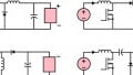
Magnetism is required for the proper operation of several electrical devices, like transformers and motors. In order for these devices to perform their functions satisfactorily, exact magnetic circuit properties must be determined. Magnetic circuits must have the correct strength, have the correct paths, and be made in suitable shapes and of suitable materials. Magnetic circuit paths may be series, parallel, or series/parallel (see Figure 1).
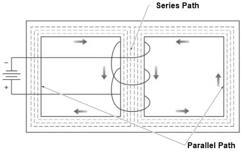
Figure 1. Magnetic circuits can have either series, parallel, or series/parallel paths.
Rowland's Law
Magnetic field lines are continuous. Magnetic circuit operating conditions are determined by calculating circuit conditions and parameters such as magnetic lines of force (magnetic flux), magnetomotive force, reluctance, the intensity of magnetizing force, permeability, hysteresis, and Permeance. These conditions and properties are calculated by applying Rowland's law.
Note
Ohm's law is used to find the level of current flow in an electrical circuit. It states that the current flow (I) in a circuit is directly proportional to the applied voltage (V) and inversely proportional to resistance (R). Rowland's law for magnetic circuits is similar to Ohm's law.
According to Rowland's law, the number of magnetic lines of force (Φ) is proportional to the magnetomotive force (Fm) and inversely proportional to the circuit's reluctance (Rm). Despite the similarities between Ohm's and Rowland's laws, a comparison reveals that each law has its own flow, force, and opposition parameters (see Figure 2).
| Electric Circuit | Magnetic Circuit | |
| Ohm's law | \[l={}^{V}/{}_{R}\] | - |
| Rowland's law | - |
\(\phi={}^{{{F}_{m}}}/{}_{{{R}_{m}}}\) |
| Flow units | ampere, l,A | flux, Φ, maxwells, webe |
| Force units | volt,V, emf, E | Fm, mmf, gilbert, ampere-turn |
| Opposition units | ohm, R, Ω | Rm, rel, gilberts/maxwell, ampere-turns/weber |
Figure 2. Despite the similarities between Ohm's and Rowland's laws, a comparison reveals that each law has its own flow, force, and opposition parameters.
Magnetic Flux
Magnetic flux (Φ) is a measure of magnetic induction, which is expressed by magnetic lines of force. See Figure 3. The maxwell (Mx), which is described as one line of flux, is the centimeter-gram-second (cgs) unit of flux. A maxwell is also characterized as a line of force. In the meter-kilogram-second (mks) system of measurement, or Système International, the Weber (Wb) is the unit of magnetic lines of force. The mks system is based on the meter and kilogram instead of the centimeter and gram in the cgs system.
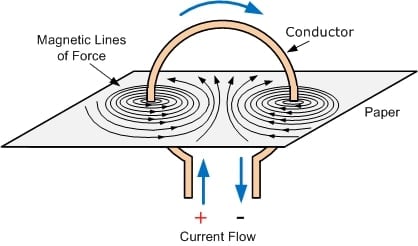
Figure 3. Magnetic Lines of Force. Image Courtesy of Brilliant
The formula to convert Weber to Maxwell is:
1 Wb = 108 × Mx
Example: What is the number of magnetic lines of force for 2,500,000 Mx?
2,500,000 Mx = 2,500,000 × 10−8 Wb = 0.025 Wb
Magnetomotive Force (MMF)
Magnetomotive force (MMF) is the current through a coil multiplied by the number of turns on the coil. Magnetomotive force, which produces the magnetic lines of force in a magnetic circuit, works on a similar concept as voltage (emf) in an electric circuit. A gilbert (Gb) is the unit of measure for MMF in the cgs system. A more common unit for mmf is ampere-turns. One ampere-turns is 1.257 gilbert.
For coils with a length that is ten times or greater than its diameter, the MMF is calculated by applying the following formula:
Fm = 1.257 × I × N
where
Fm = total circuit mmf (in Gb)
I = circuit current (in A)
N = number of conductor turns
Example: What is the total MMF for a circuit that has 4 A of current flow and 200 conductor turns?
Fm = 1.257 × I × N
Fm = 1.257 × 4.0 × 200
Fm = 1005.6 Gb