 Facebook
 Google
 GitHub
 Linkedin
LYNX: Small Footprint. Serious Power.
SD Automotive Power Modules’ next generation platform for high volume, affordable EV inverters. After Semikron and Danfoss separately defined the standards for high-performance power modules (> 250 kW), SD Automotive Power Modules is now transferring its expertise into a flexible platform for the mass market with Lynx. Defined with an optimized bill of materials, reduced manufacturing cost, and simplified integration, the Lynx platform targets 150 to 300kW SiC inverters while maintaining complete semiconductor supplier independence.
This article is published by EEPower as part of an exclusive digital content partnership with Bodo’s Power Systems.
Introduction: Semikron-Danfoss power modules such as DCM™ and eMPack™ are recognized as state-of-the-art solutions for high-performance, high-reliability xEV applications. Through innovative technologies such as Danfoss Bond Buffer® or Direct Press Die Technology®, these platforms have established new standards in reliability, power density, low inductance, and cooling performance.
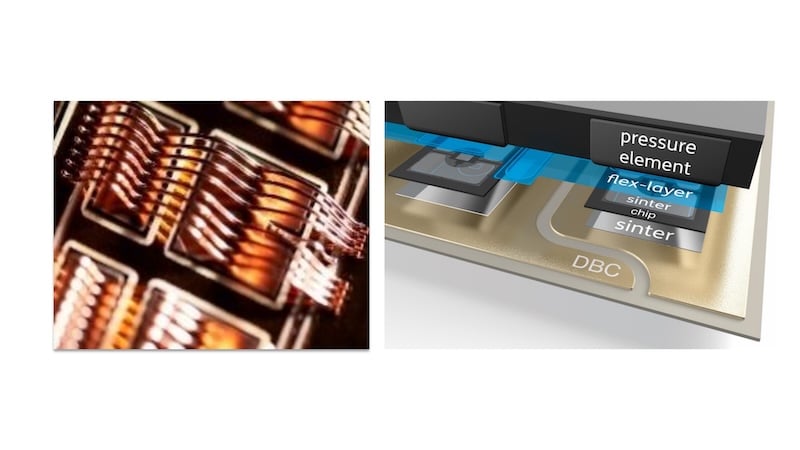
Figure 1. Danfoss Bond Buffer® (left) – Direct Press Die Technology® (right). Image used courtesy of Bodo’s Power Systems [PDF]
High-volume EV programs face increasing pressure to reduce inverter cost while maintaining efficiency, reliability, and supply-chain flexibility. The Lynx platform was developed specifically to address this challenge by combining proven Semikron-Danfoss packaging technologies with a scalable, chip-independent architecture optimized for 150-300 kW traction inverters.
Lynx Platform
Lynx is more than a power module; it’s a scalable technology platform. Based on a fully optimized transfer-molded half-bridge design that accommodates multiple chip sizes, it can be configured in a variety of architectures, including 2-level and 3-level topologies, as well as single half-bridge and six-pack assemblies. Cooling options include open or closed coolers, made of aluminum or copper, with either soldered or sintered attachment technologies.
When maximum performance is required, Lynx can be equipped with large, latest-generation SiC chips mounted on thermally optimized substrates and robustly sintered to a copper cooler. For cost-sensitive applications, smaller chip configurations combined with soldered or sintered substrate on an Aluminum cooler provide an attractive alternative. Additional configurations, including hybrid copper-aluminum coolers and closed-cooler solutions, are also possible.
The primary target market is 1200V to 1500V SiC traction inverters, although 750V SiC and IGBT variants are also being considered.
Dcm™ Proven Technologies Power Lynx
The Lynx half-bridge module benefits from DCM™ platform technologies while incorporating several significant enhancements.
As a DCM, Lynx HB uses the Danfoss Bond Buffer® technology to achieve high power density. Based on transfer molding technology, this has been demonstrated to bring a reliability improvement of more than a factor of 15 compared to conventional (Al-wires and silicone gel) power modules measured under power-cycling conditions [A].
For high thermal performance, Lynx is also based on a Silicone-Nitride (Si3N4) AMB substrate. An NTC is included for thermal monitoring, and the package is already compatible with future on-chip temperature-sensing devices.
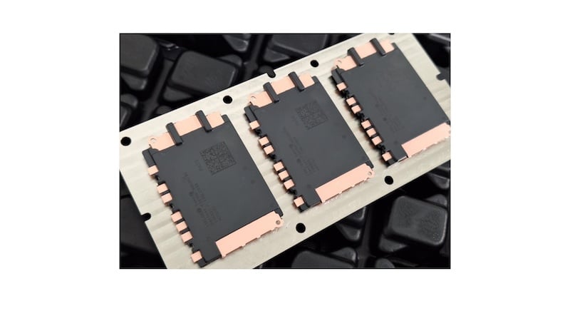
Figure 2. Lynx Power Module in six-pack configuration. Image used courtesy of Bodo’s Power Systems [PDF]
For easier integration into inverters, this module is designed to be attached to a common direct-cooled baseplate via soldering or sintering.
Lynx Further Improvements
Gate Wire / Overall Power Cycling Reliability
Compared to other modules, Lynx uses an improved gate wire type so that it’s no longer the weak point of the module during power cycling, while maintaining compatibility with standard chip metallization and production equipment. This new wire demonstrated approximately twice the power-cycling lifetime of conventional gate wires.
PCsec testing (ΔT = 130°C) demonstrated a B5 lifetime of 476,000 cycles with an 80% confidence level, compared with 262,000 cycles for the reference design.
This increased reliability enables full utilization of the extended junction-temperature capability of modern SiC devices through higher allowable temperature swings. Thus, it gives the opportunity to further optimize semiconductor chip size and product cost.
Thermomechanical Stability
Based on lessons learned from the technology development team, a more robust geometry has been developed using carefully selected materials to improve assembly robustness and thermal-shock reliability.
This can be shown by a mechanical FEM simulation comparing plastic strain on the half-bridge interface layer at low temperature between the original DCM design and Lynx (same substrate size) at -40°C, where the stress is the highest due to the maximum difference from the equilibrium temperature.
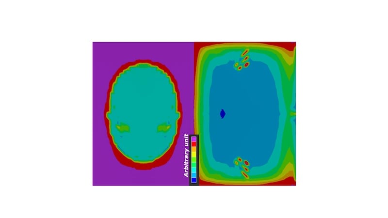
Figure 3. Plastic strain simulation at -40°C: Ref design (left) – Lynx design (right). Image used courtesy of Bodo’s Power Systems [PDF]
Thermal Performances
The improved mechanical design, including an epoxy mold compound with a higher glass-transition temperature (Tg), further extends the package’s thermal operating range. Lynx is designed to fully leverage the capabilities of the latest SiC technologies, supporting junction temperatures (Tj) exceeding 200°C. The platform is targeted for qualification at a continuous Tj of 200°C, with transient operation up to 225°C for limited durations.
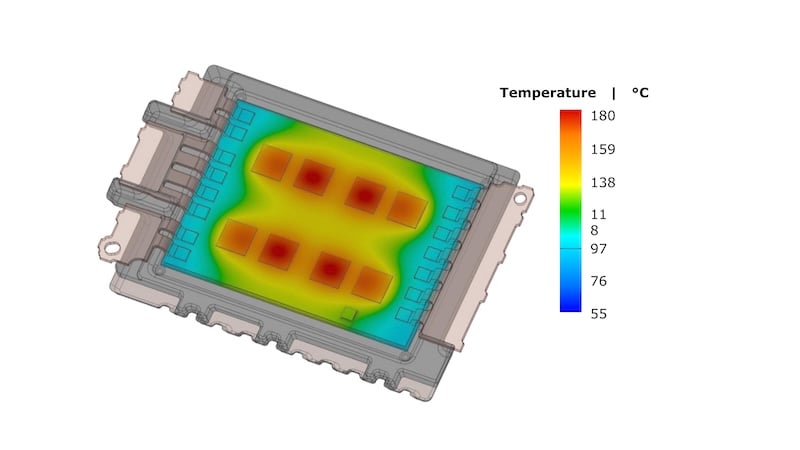
Figure 4. Example of Lynx chip's thermal map in steady state. Image used courtesy of Bodo’s Power Systems [PDF]
On the thermal transfer side, system sintering onto a Cu-cooler remains a best-in-class solution for heat extraction. The additional cost associated with sintering can be offset by reduced semiconductor chip area requirements resulting from higher achievable power density.
Electrical Interfaces
For better inverter integration, on top of cooler flexibility already discussed, Lynx offers open top-side terminals compatible with standard automotive assembly processes.
Power leadframes are designed for laser welding. The three-DCterminal configuration, together with an optimized internal layout, enables low stray inductance and supports high-speed, low-loss switching.
Control terminals are ready for ultrasonic or laser-welded pins. Pins are attached after six-pack assembly, enabling high positional accuracy and simplified gate-driver integration.
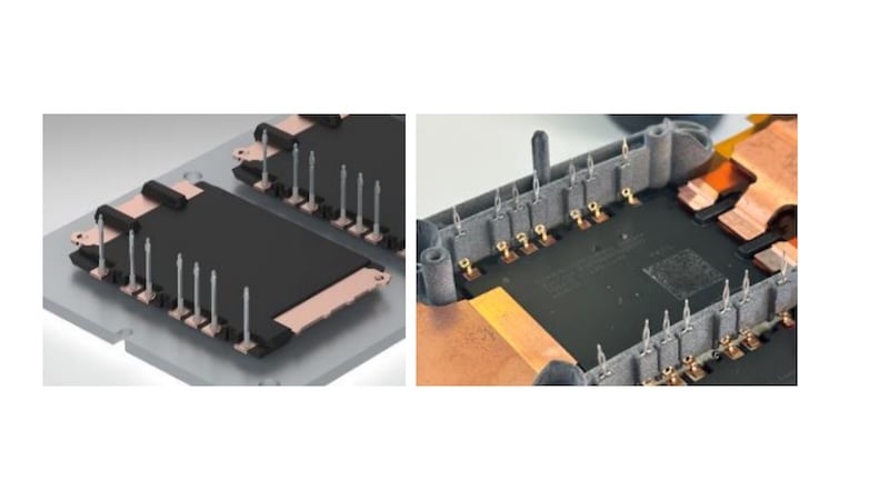
Figure 5. US welded pins (top) – laser pins (bottom). Image used courtesy of Bodo’s Power Systems [PDF]
Lynx Boosts Drivetrain Performance
Stray Inductance
Module layout has been optimized to reduce stray inductance. Together with the 3 DC lead configuration, the complete DC+ to DC- loop inductance is limited to less than 4nH including the power terminals.
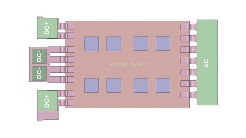
Figure 6. Model for stray inductance calculation (indicating chip position). Image used courtesy of Bodo’s Power Systems [PDF]
Switching Behavior
Figure 7 presents measured switching waveforms for a module equipped with four 25mm² Gen 4 chips operating at 850VDC and 800A at room temperature. Further optimization is possible through reduced DC-link inductance and lower gate resistance values.
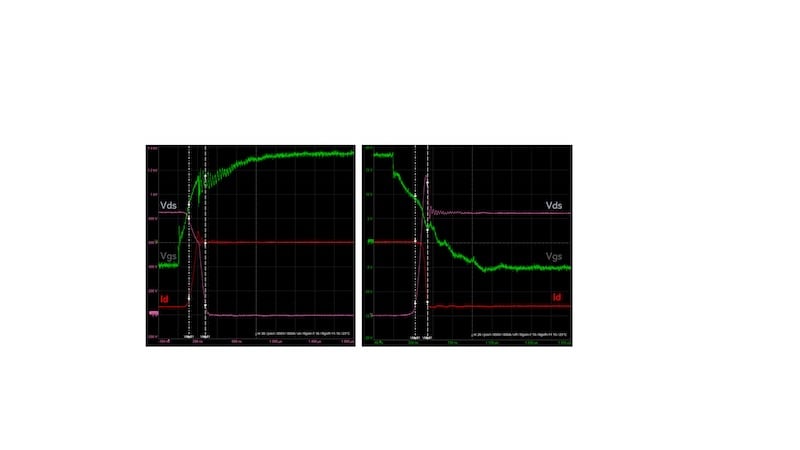
Figure 7. Switching waveforms (measured) for 4x25mm² 1200V Gen4 chips configuration. Image used courtesy of Bodo’s Power Systems [PDF]
Robustness in short-circuit conditions (shoot-through) has also been evaluated, showing stable switching behavior. The module proved to be more robust than the chips.
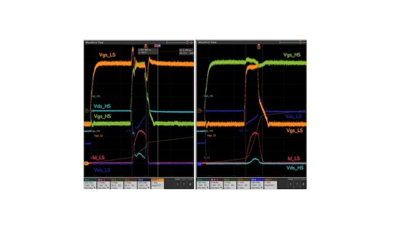
Figure 8. Short-circuit example waveforms. Image used courtesy of Bodo’s Power Systems [PDF]
The module design and layout are safe regarding chip parallelization and short-circuit behavior. Full switching losses and short-circuit capability will be validated with final chips.
Thermal Resistance
Thermal resistance has been simulated for several cooler configurations, including pin-fin Cu cooler (sintered or soldered) and pin-fin Al cooler (soldered).
Figure 9 shows simulation and measurement results for different cooler and chip size configurations.
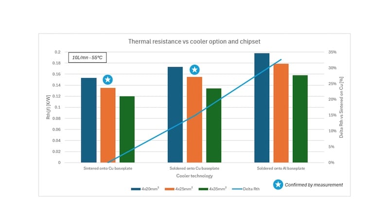
Figure 9. Junction-to-fluid thermal resistance. Image used courtesy of Bodo’s Power Systems [PDF]
Ampacity
Figure 10 illustrates the calculated Lynx junction temperature as a function of output current using Gen5 chip technologies from four leading suppliers.
With an ampacity (current carrying capability) reaching 700 Arms at a maximum Tj of 200°C, a fully populated Lynx module addresses even the most demanding traction inverter applications. Reduced chip area configurations are also available to enable cost-optimized solutions.
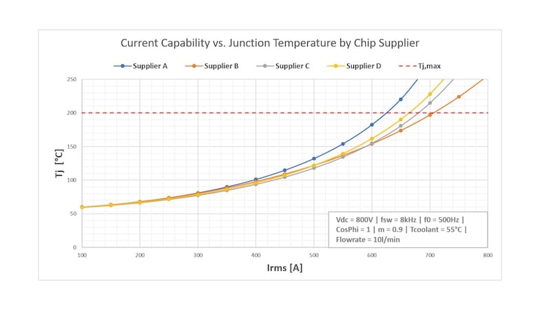
Figure 10. Typical Junction temperature vs. current. Image used courtesy of Bodo’s Power Systems [PDF]
Chip benchmarking confirms varying performance-to-cost trade-offs among suppliers. Thanks to the company’s chip-independent approach, the optimal balance between performance and system cost can be selected for each customer application.
Thermal Shock Reliability (TST)
Thermal cycling reliability has been evaluated with both sintered and soldered pin-fin Cu-coolers. An accelerated liquid-to-liquid (LtL) thermal shock test has been developed to confirm reliability improvement. Thanks to the LtL test method, reliability can be assessed approximately five times faster than with conventional thermal shock testing. More insights into this test method will be presented during the 2027 PCIM Expo in Nuremberg.
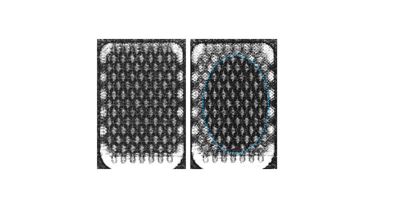
Figure 11. SAM picture of system sintering layer (Reference) initial (left) – after 250c (right). Image used courtesy of Bodo’s Power Systems [PDF]
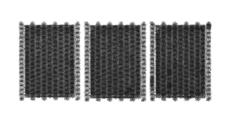
Figure 12. SAM picture of system sintering layer (Lynx Module) initial (left) – after 250c (middle) – after 1000c (right). Image used courtesy of Bodo’s Power Systems [PDF]
Figures 11 and 12 compare scanning acoustic microscopy (SAM) pictures from our reference and new Lynx platforms. Both share the same substrate size and are sintered onto a Cu-cooler. When our former platform is significantly degraded after 250 cycles (-40/140°C, liquid-to-liquid), Lynx shows virtually no observable degradation even after 1000 cycles.
What More?
Further Cost Reductions
Alternative paste for system sintering is currently under development. Early results indicate that Lynx modules can be attached to coolers using cost-effective sintering processes while maintaining the same reliability performance demonstrated with existing materials. These advances in materials, design, and process technology are expected to significantly reduce manufacturing costs, bringing system-sintering price close to that of conventional soldering while preserving superior cooling performance and reliability.
In parallel, the latest semiconductor technologies from established and emerging chip suppliers are continuously benchmarked to ensure the best possible combination of performance, availability, and cost competitiveness for customer applications.
Three-Level Configurations
For additional drivetrain efficiency improvement, a 3-level variant is under development. T-type phase-leg topology will be used with 1200V and 750V SiC MOSFETs, respectively, on the vertical path (T1 and T4) and horizontal path (T2 and T3).
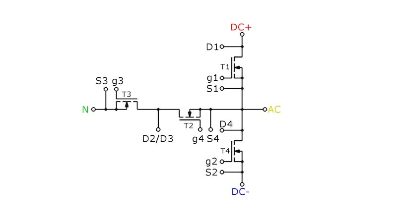
Figure 13. 3-level T-type topology (common drain). Image used courtesy of Bodo’s Power Systems [PDF]
Different implementations can be selected depending on the motor-control strategy. A “symmetric” ampacity design will allow utilization of 3-level motor control for full power, leading to about 350Arms max ampacity. If 3-level operation is required only in efficiency-critical operating regions, while full-power operation can rely on conventional 2-level control, an asymmetric layout can be adopted, leading to a max ampacity of about 250Arms in 3-level and about 450Arms in pure 2-level PWM.
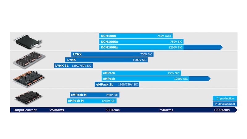
Figure 14. SD APM platforms roadmap. Image used courtesy of Bodo’s Power Systems [PDF]
Conclusion
The Lynx platform combines proven high-performance power module technologies with the flexibility and cost efficiency required for the next generation of high-volume electric vehicle applications. Building on the expertise gained from previous Semikron-Danfoss platforms, Lynx delivers enhanced electrical and thermal performance, extended operating temperature capability, and significantly improved reliability through optimized design and manufacturing processes.
Its flexible architecture enables adaptation to a wide range of inverter requirements, including different semiconductor technologies, chip suppliers, cooling concepts, and cost targets. This chip-independent approach provides customers with the freedom to select the optimal performance-to-cost balance without compromising system robustness or efficiency.
Developed and manufactured in Germany, the Lynx platform is designed to support the growing demand for scalable, affordable, and high-performance EV traction inverters. Engineering samples are available today, and the platform is well positioned to support future vehicle electrification programs.
About SD Automotive Power Modules
Product Portfolio
SD Automotive Power Modules currently offers four major product platforms, as shown in picture 14.
DCM1000 / DCM1000x is available in IGBT 750V and SiC 750V and 1200V. The platform currently supports up to 800 Arms, with further developments targeting 1000 A and beyond.
Lynx is planned for 2029 series production. Samples are already available.
eMPack is currently in series production with 750V and 1200V SiC configurations up to 850Arms. A 3-level variant is available as engineering samples, and additional developments are underway to further increase ampacity.
eMPack M is a more compact variant of eMPack, already in series production in a customized version. It can drive up to 550Arms in 750V or 1200V SiC.
Engineering and Production Service
In addition to its standard product portfolio, SD automotive power modules can support your demands for:
- Custom specific module demand (series products);
- Design engineering service to design your custom power module, even without series production planned in SD;
- Process engineering service to define your process chain, set up your processes and equipment, or solve your manufacturing issues;
- Samples or series production service.
Please contact us for further information and samples.
Reference
[A] A. Streibel et al., “Reliability of SiC MOSFET with Danfoss Bond Buffer Technology in Automotive Traction Power Modules,” PCIM Europe 2019; International Exhibition and Conference for Power Electronics, Intelligent Motion, Renewable Energy and Energy Management, Nuremberg, Germany, 2019, pp. 1-7.
This article originally appeared in Bodo’s Power Systems [PDF] magazine and is co-authored by Gael Blondel, Erk Petersen, Martin Becker, Mohammad Goushegir, Joan Pons, Jörg Bergmann, and Ole Mühlfeld; SD Automotive Power Modules, Germany