Facebook
 Google
 GitHub
 Linkedin
Distribution Transformers—Part 5: Line Voltage Regulators and Capacitor Banks
Learn how line voltage regulators and capacitor banks provide fine control of feeder voltage profiles and reactive power balance, ensuring stability across evolving grid conditions and DER growth.
Maintaining service voltages within acceptable bands on modern feeders is a dynamic task influenced by load diversity, conductor impedance, and the growing presence of distributed energy resources (DER). Distribution transformers interface the medium‑voltage network with utilization voltages, while line voltage regulators and capacitor banks provide fine control of feeder voltage profiles and reactive power balance. Together, these assets support the voltage ranges defined for 60 Hz systems and equipment and help utilities satisfy steady‑state limits at service points under normal operating conditions.
Line Voltage Regulators
Autotransformer‑based step‑voltage regulators inject a controlled series voltage in phase with the line to raise or lower feeder voltage. A reversing switch selects boost or buck, and a load‑tap‑changing (LTC) mechanism moves through discrete taps to modulate the injected series voltage. Regulators are commonly deployed as single‑phase units that can be banked for three‑phase feeders, with neutral and insulation designs suited to overhead or pad‑mounted installations. Device requirements, test methods, and control features for step-voltage regulators are specified in IEEE/IEC C57.15-2017.
In typical utility practice, many step‑voltage regulators provide a regulating range of about ±10% around nominal in 32 steps, yielding approximately 0.625% per tap. This granularity allows precise adjustment of feeder voltage to maintain service targets without excessive tap motion. The tap changer’s duty cycle, bypass arrangements, and protection coordination are addressed in IEEE C57.131, which defines ratings, performance, and application considerations for different feeder topologies and duty profiles.
Placement strongly influences regulator effectiveness. Mid‑feeder installations are chosen when upstream substation voltage is well controlled and the voltage drop along the primary laterals requires mid‑span support to keep downstream nodes within limits across load cycles. End‑of‑line regulators are favored where long laterals or rural feeders exhibit pronounced voltage sag at remote points; situating the regulator near the weakest node maximizes benefit to the farthest customers and can defer conductor upgrades. IEEE/IEC C57.15 informs these application choices by defining regulator ratings, test methods, control ranges, thermal capabilities, and insulation coordination requirements for different feeder conditions.
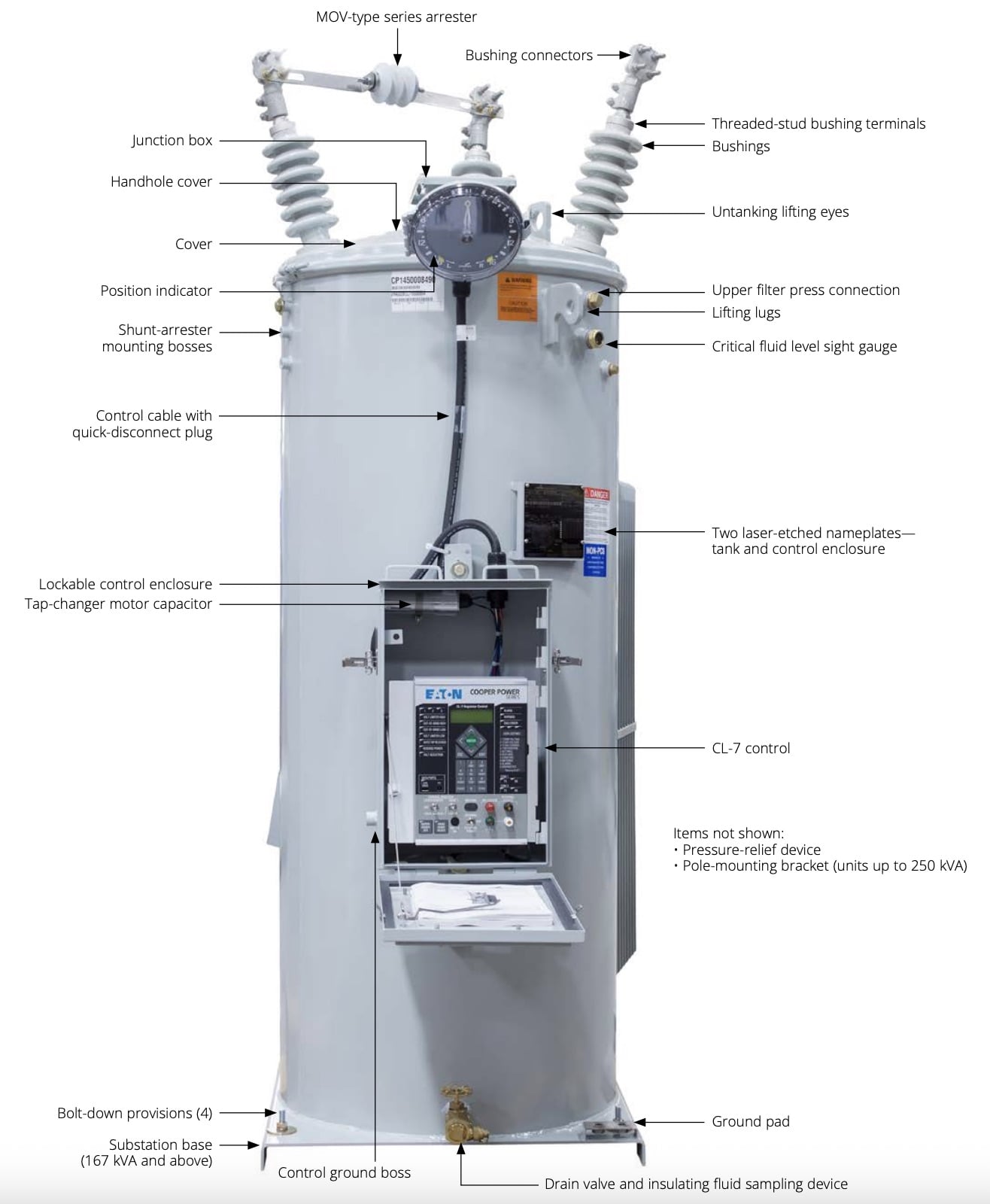
Single-phase step-voltage regulator. Image used courtesy of Eaton. (Click on image to enlarge).
Regulator Control Schemes
Modern controls sense feeder current and voltage and calculate an effective remote or local voltage setpoint, advancing or retarding taps as needed while enforcing time delays to avoid unnecessary operations. Line Drop Compensation (LDC) is a foundational method: the controller estimates the voltage at a user‑defined “line‑drop compensated” point by modeling series drop using R and X settings representative of the feeder segment.
By targeting the compensated voltage rather than the terminal voltage, the regulator holds remote nodes near a desired band across load variation. This capability is described in IEEE/IEC C57.15 and remains a central feature of utility regulator settings.
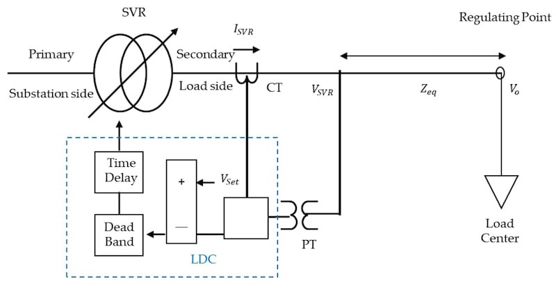
Operation structure of Line Drop Compensation (LDC). Image used courtesy of MDPI.
Time‑delay coordination is essential for stable operation. Controls commonly apply an intentional delay before each tap change, allowing transient events, motor starts, or feeder reconfiguration to settle before mechanical motion occurs.
When multiple regulators exist in series—such as a substation LTC followed by mid‑feeder regulators—delays are coordinated so upstream devices act first on bulk changes, and downstream devices correct residual error. Such sequencing reduces hunting and extends tap changer life while preserving voltage targets defined for service and utilization ranges.
Increasing DER penetration introduces forward and reverse power flow conditions that legacy schemes did not always anticipate. In reverse flow, current direction and the reactive power sign can invert the net voltage impact of feeder impedance.
Modern regulator controls therefore include forward/reverse detection and separate LDC parameters for each direction, ensuring correct compensation whether midday photovoltaic export or nighttime load dominates. The need for such behavior aligns with the broader voltage‑regulation expectations associated with DER interconnection frameworks.
Capacitor Banks for Reactive Power Support
Shunt capacitor banks supply reactive power locally, reducing current on upstream conductors and producing a measurable voltage rise at nearby nodes. Fixed banks provide continuous reactive support and are often placed at locations with stable inductive demand, such as feeders serving industrial motors.
Switched banks use vacuum switches or contactors under controller supervision to add or remove kVAr in stages in response to measured voltage, power factor, reactive power, or time schedules. Application and protection practices for shunt capacitors, including fusings, discharge resistors, and unbalance detection, are detailed in IEEE 1036.
Three principal benefits drive capacitor deployment on distribution feeders:
- Voltage support: Supplying kVAr near the load reduces reactive current in the line segment between the source and the bank, decreasing the series voltage drop and raising local voltage. This is particularly effective near the end of long laterals where regulator placement may be impractical.
- Loss reduction: Lower line current reduces I²R losses across conductors and transformers, improving feeder efficiency during inductive loading periods. Coordinating bank sizes and locations with feeder impedance data maximizes this benefit.
- Power factor correction: Banks improve substation and feeder power factor, freeing capacity on transformers and potentially reducing charges tied to reactive demand where applicable. Sizing and control considerations that balance local voltage rise with system‑wide kVAr targets are covered in IEEE 1036.
Control sophistication ranges from local voltage–or kVAr–based logic to centralized schemes that dispatch multiple switched banks using feeder telemetry. Local control remains effective and resilient, especially when communications are limited. Centralized control—through an advanced distribution management system—can coordinate banks with regulators to maintain a flatter voltage profile, minimize losses, and avoid oscillations between independently acting devices.
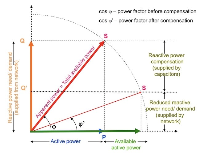
Reactive power compensation using capacitors. Image used courtesy of ABB.
Device Placement
| Device | Common Placement | Primary Objective |
| Step-voltage regulator | Mid-feeder | Flatten voltage profile across broad load area |
| Step-voltage regulator | End-of-line | Lift remote node voltage under heavy loading |
| Shunt capacitor bank | Mid- to end-feeder | Supply reactive power locally |
| Substation capacitor bank | Source bus | Improve substation power factor |
Control and Coordination
Coordinating local controls with centralized strategies is increasingly important as DER participation grows. Local schemes retain fast, deterministic action and continue to hold voltage during communications outages. Centralized Volt/VAR optimization (VVO), in contrast, evaluates feeder‑wide data and topology to schedule regulator setpoints, tap deadbands, and capacitor stages for system objectives such as loss minimization or conservation voltage reduction while respecting voltage limits. Aligning local deadbands and time delays with supervisory setpoint intervals prevents “dueling controllers” and reduces unnecessary tap or switching counts.
Interaction between regulators and smart inverters adds another layer. Modern interconnection requirements define Volt‑VAR functions in which DER inverters inject or absorb reactive power as a function of local voltage. When inverters provide dynamic kVAr near endpoints, mid‑feeder regulators can operate with reduced LDC aggressiveness or wider deadbands, because voltage excursions are partially corrected where they originate. Coordination requires selecting Volt‑VAR curves, deadbands, and priority (real‑power vs reactive) consistent with feeder objectives and thermal constraints.
Special attention is required under light load and high DER export. Fixed capacitors that improve voltage during evening inductive loading can cause overvoltage on sunny, low‑load afternoons when DER injects real power and local kVAr demand diminishes. In such scenarios, end‑of‑line voltage may rise even if regulator taps are lowered.
Mitigations include converting fixed to switched banks at sensitive nodes, enabling time‑of‑day or seasonal schedules, and adjusting LDC parameters for reverse power conditions so that regulators do not inadvertently boost when export prevails. Where smart inverters operate in Volt‑VAR mode, set curves with modest reactive gain near nominal can further dampen excursions without provoking control conflicts.
Device capability and standardization matter as feeders grow more interactive. IEEE/IEC C57.15 specifies electrical, mechanical, and control requirements for step-voltage regulators, including test codes for tap changers, dielectric strength, and functional control tests.
On the capacitor side, IEEE 1036 addresses protection schemes, unbalance detection for grounded-wye and ungrounded banks, and interactions with feeder harmonics. Aligning field settings and asset selection with these standards helps ensure that operational behavior matches planning studies.
Careful Attention Required
Distribution transformers connect the medium‑voltage grid to utilization levels, but feeder‑wide voltage quality depends on how line voltage regulators and capacitor banks are specified, placed, and coordinated.
Autotransformer‑based regulators provide granular boost or buck through discrete taps, with LDC and time delays shaping stable responses across varying load and power‑flow directions. Shunt capacitors provide local kVAr, lifting voltage and reducing losses when inductive demand dominates, while switched banks and Volt‑VAR‑capable inverters adapt support to changing conditions. Effective coordination—local and centralized—links these assets to system objectives and to steady‑state voltage ranges.
As DER grows, careful attention to forward/reverse logic, capacitor staging, and Volt‑VAR settings will keep feeders compliant, efficient, and resilient under an increasingly diverse set of operating scenarios.