Facebook
 Google
 GitHub
 Linkedin
LTO Batteries for Peak Shaving in Mobile and Stationary Applications
This article explains the battery requirements involved and highlights the unique characteristics of Lithium Titanium Oxide (LTO) batteries compared to other battery chemistries.
This article is published by EEPower as part of an exclusive digital content partnership with Bodo’s Power Systems.
Peak shaving refers to the targeted reduction of peak loads on the consumer side through the use of supportive battery systems to efficiently cover short-term energy demands. This does not involve increasing energy generation, but rather using stored energy to offset temporary peaks.
Many companies have highly fluctuating energy demands, for example, in generator and crane applications, which can involve the simultaneous operation of several machines, the startup of production systems, or the heating of boilers. Without buffering these peak loads, grid connections or generators would have to be dimensioned for the maximum peak load, resulting in high costs and inefficient use.
Why Peak Shaving?
The main goal of stationary battery storage systems is to store energy. In photovoltaic (PV) systems, for instance, energy generated when the sun is shining is stored and used at a different time when needed. This creates requirements for maximum capacity at minimum cost. The key metric is the cost in euros per kilowatt-hour (kWh) of installed capacity.
However, this capacity is used relatively infrequently. In PV systems, the battery is charged and discharged at most once per day, usually only a fraction of a full cycle, and at a slow rate over several hours. The situation is entirely different in peak shaving. Here, the battery is not used to store energy but rather to deliver the power needed to balance load peaks. The primary demands on the battery are reversed: instead of maximizing capacity, the aim is to deliver as much power as possible with minimal capacity.
The more frequently the battery can help avoid peaks, the greater its value. The main objective of a peak shaving battery is therefore not to store a lot of energy, but to use the stored energy as efficiently as possible. The decisive cost factor is euros per GWh of energy used over its lifetime. This results in the following requirements:
Battery Requirements for Peak Shaving
Batteries for peak shaving must withstand a very high number of charge and discharge cycles. While a PV system might complete an average of 0.5 cycles per day, adding up to 1,800 full equivalent cycles over ten years, a peak shaving battery used 10 times a day must withstand 36,500 cycles over the same ten-year period. These cycles generally contribute to the ageing of lithium-ion batteries. The number of possible cycles strongly depends on the specific energy density of the battery cells. The higher the energy density, the faster the cells age due to cycling.
Lithium nickel manganese cobalt oxide (NMC) cells with the highest energy densities of over 250 Wh/ kg last only a few hundred cycles before reaching end-of-life at 80% of their original state-of-health (SoH) capacity. Lithium iron phosphate (LFP) cells with a slightly lower energy density of around 150 Wh/kg usually last a few thousand cycles. LTO (Lithium Titanium Oxide) cells store the least energy (~100 Wh/kg) but can withstand tens of thousands of cycles even under demanding load profiles.
Another challenge is the significantly higher charge rate (C-rate) in peak shaving. The C-rate indicates how fast a cell can be charged or discharged relative to its capacity. For example, a 10 Ah cell charged at 10 A is at 1 C and would fully charge in one hour. If large load peaks are to be covered with a small battery, the cells must withstand high C-rates during discharge and recharge. C-rates also affect battery ageing.
Rapid charging above 1C accelerates ageing in NMC and LFP cells. The graphite anode cannot absorb lithium ions quickly enough, leading to lithium plating (discussed below), especially at low temperatures and high state-of-charge (SOC). This issue does not occur with LTO cells. LTO offers high power density and can be charged and discharged at high C-rates within minutes.
Even under continuous 5C/5C usage, an LTO cell survives tens of thousands of cycles. Using conventional Li-ion batteries (NMC or LFP) for peak shaving, therefore, requires significant oversizing. This reduces C-rates to acceptable levels but increases footprint, weight, and cost. Despite this, ageing remains a limiting factor, and regular battery replacement is needed. LTO technology can prevent premature replacement, and its compact design reduces both size and cost. The next section illustrates this with a hybrid generator example.
Advantages of LTO Batteries: An Example
Hybrid generators, commonly found in mining, construction, outdoor events, and telecommunications, often operate under harsh environmental conditions and extreme temperatures, and comprise conventional diesel or gas internal combustion engines with battery storage systems to manage load peaks efficiently.
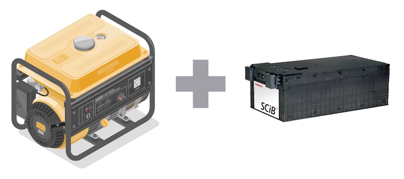
Figure 1. The use of LTO batteries in mobile hybrid generators enables the use of generators with lower output. Image used courtesy of Bodo’s Power Systems [PDF]
By integrating a battery, short-term peak loads are absorbed so that the generator does not need to be designed for extreme peak loads. This allows the generator to operate continuously in its optimal power range, increasing reliability and enabling a smaller and thus more cost-efficient generator. In the economic evaluation of battery systems for hybrid generators, the total cost of ownership (TCO) is a crucial factor.
The following sample calculation illustrates why LTO batteries, despite higher costs per kWh, can represent a more economical solution than LFP batteries. A key advantage of LTO batteries is their ability to handle high charge and discharge currents, allowing them to be dimensioned much smaller for the same application. In this example, the LTO battery has a capacity of only 15 kWh, whereas a comparable LFP solution requires 60 kWh — four times as much.
Although the relative price per kWh for LTO is assumed to be three times higher than for LFP, the acquisition cost of the battery remains lower (45 vs. 60). However, the LTO battery must perform four times more cycles per day with the same energy throughput. Despite the more intensive usage, the service life of the LTO battery is about twice as long as that of the LFP battery. Thus, the TCO over 10 years clearly favors LTO:
Table 1. Toshiba LTO batteries achieve lower TCO compared to LFP cells.
| LTO | LFP | |
| Capacity [kWh] | 15 | 60 |
| Relative price/kWh | 3 | 1 |
| Total relative cost | 45 | 60 |
| Equivalent full cycles per day | 8 | 2 |
| Lifetime [y] | 10 | 5 |
| Relative TCO for 10 years | 45 | 120 |
Although LTO initially appears more expensive, the higher cycle stability and smaller system size significantly reduce long-term costs. The LFP battery would need to be replaced within 10 years, thereby increasing the TCO.
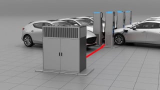
Application Example: Container Crane Systems
Modern container cranes face the challenge of handling high peak loads while simultaneously reducing operating costs and environmental impact. Hybrid crane solutions with high-performance battery storage systems enable significant efficiency gains through peak load management, energy recovery, and reduced dependence on diesel generators.
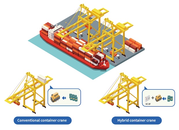
Figure 3. In hybrid hoisting or gantry cranes, LTO cells can reduce the consumption of fossil fuels from diesel generators (bottom right). Image used courtesy of Bodo’s Power Systems [PDF]
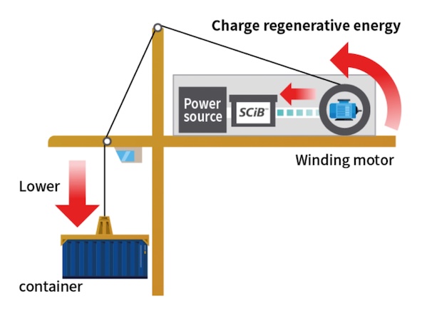
Figure 4. The motion or gravitational kinetic energy generated when lowering loads is fed back into the battery. Image used courtesy of Bodo’s Power Systems [PDF]
The hybrid energy system for container cranes in the example combines a 63kWh LTO battery (SCiB™ high-power modules, 19s3p) with a 30kW diesel generator. This means that the battery with an energy of 63 kWh consists of a configuration of 19 modules in series and 3 in parallel. A total of 57 modules are therefore installed in this battery. Each module in turn consists of a configuration of cells connected in series and parallel. Normally, it is then a 2p12s module. Depending on the application, Toshiba’s standard or high-power cells (HP suffix) are used.
While crane operation temporarily demands power levels of 250 to 300 kW, the battery can absorb these load peaks and relieve the generator. As a result, a significantly smaller diesel generator unit is needed, reducing fuel consumption and emissions. Additionally, more than 10% of the energy is recovered through recuperation, further improving overall energy efficiency
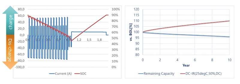
Figure 5. Example load profile of a hybrid crane application. Image used courtesy of Bodo’s Power Systems [PDF]
Figure 5 shows the load profile of this application at the cell level. The battery cells must withstand very high charge and discharge currents of 3–4 C to reliably manage the dynamic load fluctuations. With 14 hours of operation per day (7 load cycles), this results in a daily energy throughput of 471 kWh. This means the battery undergoes 27,375 equivalent full cycles over 10 years.
Despite this demanding load profile and extreme cycle stress, the LTO cells retain a remaining capacity of 96 % after 10 years. The combination of a high-performance LTO battery and a reduced diesel generator represents a future-proof solution for the hybrid operation of container cranes.
In addition to significant fuel and emissions savings, operators benefit from lower maintenance requirements, stable operating costs, and an extremely long battery lifespan. Thanks to the high performance and recuperation capability, this system offers a sustainable and economical alternative to conventional drive systems in port operations.
LTO Battery Cell Compared to LFP and NMC Cells
Why LTO cells can withstand very high charging currents, enable a long service life, and are simultaneously extremely safe lies in the technical design of the Li-ion cell. Each cell is essentially based on four functional components: anode, cathode, separator, and electrolyte. While the cathode side is implemented with different materials depending on the desired cell characteristics, such as LFP or NMC, conventional cells almost exclusively use graphite as the anode material.
A key exception is the LTO cell, whose electrochemical behaviour fundamentally differs from classical cells due to the use of Lithium Titanium Oxide as the anode material. The anode material used has a decisive influence on a number of electrochemical and physical properties of the cell. In particular, it affects the electrochemical potential of the anode relative to lithium, which in the case of graphite is around 0.1–0.2 V, only slightly above that of metallic lithium.
This proximity enables a high cell voltage and thus high gravimetric and volumetric energy density. However, graphite is thermodynamically unstable in this potential range when in contact with the liquid electrolyte. This leads to the electrochemical decomposition of the electrolyte and the formation of what is known as the solid electrolyte interphase (SEI).
The SEI acts as a necessary passivation layer that prevents further reactions with the electrolyte. However, it is also an electrochemically inactive component, whose growth over time causes a gradual reduction in cell capacity and an increase in direct current internal resistance (DCIR). Repeated cycles or prolonged storage at elevated SOC levels can cause continuous growth of this layer, which is considered one of the main causes of calendar ageing. In contrast, the LTO anode exhibits a significantly higher electrochemical potential of about 1.55V vs. Li/Li+.
This voltage is sufficiently distant from the reduction potential of the electrolyte, meaning no SEI formation is necessary. The material displays electrochemically nearly inert behaviour toward the electrolyte. This property has several significant advantages: there is no electrochemical decomposition, ageing behaviour is minimal, and the cell maintains stable performance over very long periods with consistently low DCIR.
Disadvantages and Advantages of LTO Cells
One disadvantage of this high anode potential, however, is the reduced cell voltage, which for LTO cells typically lies around 2.4 V, compared to 3.2–3.7 V for LFP or NMC cells with graphite anodes. Consequently, the specific energy density of LTO cells is significantly lower than that of their conventional counterparts.
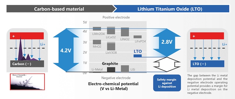
Figure 6. Differences in electrochemical potential ensure maximum safety. Image used courtesy of Bodo’s Power Systems [PDF]
In addition to electrochemical stability, LTO also offers critical advantages in terms of the mechanical integrity of the cell. While graphite experiences a volume change of up to 10% during the insertion and extraction of lithium ions, which can lead to structural damage and cracking of the SEI, LTO, due to its spinel structure, displays what is known as “zero strain” behaviour. The volume change during (de-)lithiation is less than 0.5 %, thereby avoiding mechanically induced degradation processes. This results in exceptionally high cycle stability.
Properly designed cells can achieve over 20,000 full cycles while retaining more than 90 % of their original capacity. Such capacity retention under extreme conditions, including charge/discharge rates of 5 C (50 A), an ambient temperature of 35 °C, and a full state-of-charge range (0–100 % SOC), is not achievable in conventional Li-ion cells. The corresponding test results are documented in Figure 7.
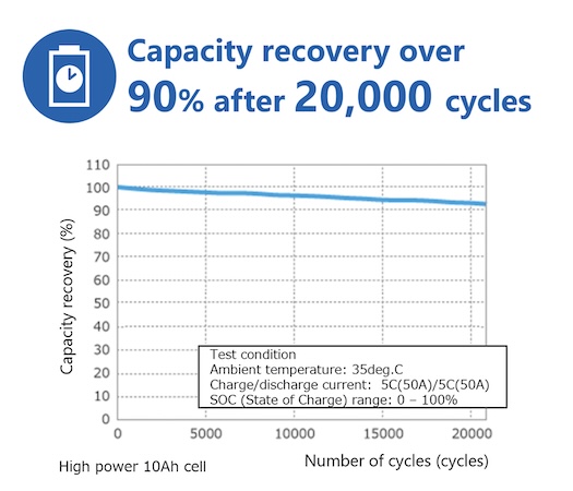
Figure 7. Long-term measurement of capacity retention after 20,000 cycles of an SCiB 10 Ah cell. Image used courtesy of Bodo’s Power Systems [PDF]
Another major advantage of LTO anodes relates to charging behaviour. When using graphite, there is a risk of so-called lithium plating at high charge rates, low temperatures, or high SOC. In this case, lithium ions are no longer intercalated but deposited as metallic lithium.
This effect can not only lead to further SEI growth and thus accelerated ageing, but in some cases also lead to the formation of needle-like dendritic structures that can penetrate the separator and cause internal short circuits. LTO, by contrast, is capable, due to its spinel structure, of intercalating lithium ions extremely quickly and uniformly without plating.
This allows high charging speeds across a broad range of temperatures and SOC levels and makes LTO cells one of the few cell technologies capable of true fast charging with full depth of discharge (DoD). Finally, the absence of SEI and resistance to plating results in significantly greater operational safety. On one hand, the LTO anode prevents the formation of dendrites, which could otherwise lead to safety-critical short circuits.
On the other hand, in the event of a short circuit — for example, due to mechanical damage — a fully discharged LTO cell discharges only slowly due to its high resistance, significantly reducing the risk of thermal runaway (see Figure 8). Moreover, the classic trigger for thermal chain reactions — the thermal decomposition of the SEI — is absent in LTO cells, which gives them greater thermal stability compared to conventional Li-ion cells.
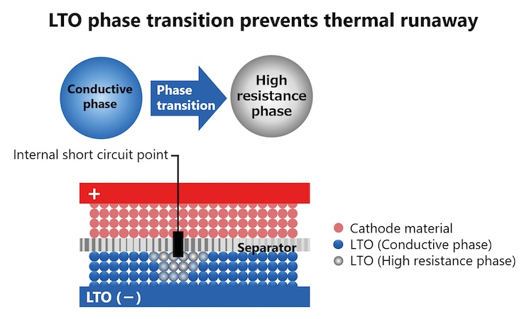
Figure 8. LTO phase transition prevents thermal runaway. Image used courtesy of Bodo’s Power Systems [PDF]
This article originally appeared in Bodo’s Power Systems [PDF] magazine.