Facebook
 Google
 GitHub
 Linkedin
Insulation Coordination Strategies for Series-Connected Multi-Terminal HVDC Systems
Learn how to optimize and design a reliable insulation framework for an HVDC network, focusing on aspects like insulation clearance, voltage surge modelling, and material selection.
In series-connected multiterminal HVDC (MT-HVDC) networks, converters are often arranged in a stacked configuration with increasing voltage levels, with only a single point connected to ground. This arrangement with ascending potential creates a unique electrical stress pattern that requires careful consideration.
In this article, we’ll look at, in a structured approach, insulation coordination methodology that includes guidelines based on IEC 6007, material behaviour under partial discharges, overvoltage simulation, and long-term mitigation of electrical stress.
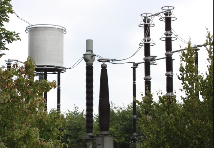
Figure 1. High-voltage ceramic insulators in a converter station play a crucial role in the insulation coordination system by providing dielectric isolation and mechanical support for high-voltage termination. Image used courtesy of Wikimedia.
Insulation Challenges in Series Connected HVDC Architecture
The fixed voltage levels of each converter station with respect to ground in traditional HVDC systems result in a relatively straightforward insulation coordination strategy. However, in series-connected systems like the ones in MT-HVDC grids and offshore transmission platforms, the situation becomes more complex.
This system presents a new insulation challenge due to varying voltage levels, grounding configurations, and dynamic fault behaviour of the converter stations. The floating voltage of each station, in this series system, is not all referenced to the same ground potential. For instance, in a three-terminal 900 kV system, the station is arranged at different voltage levels, with the first terminal, A, at a fixed voltage of +300 kV, which is grounded; the second and third terminals, B and C, are at higher floating voltage levels of +600 kV and +900kV, respectively.
In such a system, only the lowest voltage terminal is grounded. In contrast, the other terminals operate at a floating potential, leading to an electrical field pattern across the insulation that induces a number of challenges to the system.
Floating Potential
These challenges are induced by the floating potential, where each of the terminals employs active and passive systems, such as resistive or capacitive voltage dividers, to regulate their potential and balance voltage across connected components. Another notable challenge is the unreliability of the ground reference insulation monitoring method. In this case, specialized isolation-based systems, such as those using high-voltage signal isolators or fiber optics, are necessary to measure leakage current and insulation resistance in the system accurately.
The proximity of floating components to the ground structure develops a notable high-voltage gradient over short distances. To resolve the risk of corona discharge or surface flashover, the extreme use of field gradient devices, like stress cones, rings, and shield electrodes, is necessary, especially on terminations and bushings.
Another notable insulation challenge is electrical stress distribution, where the varying electrical field pattern across converter stations during brief transients, fault clearing, or switching of polarity, poses a significant challenge for insulation design.
Under normal operating conditions, converter insulation is subject to a DC voltage referenced to ground or adjacent floating terminals. But in the event of a fault, such as a short circuit to ground, there is an asymmetrical voltage distribution that needs a conservative insulation dimensioning with extra safety margins.
Clearance and External Insulation Design
Reliability and safety of HVDC systems are essential even during faults. When multiple converters are connected in series, the insulation design of each terminal carrying different potentials involves the process of determining clearance distances, DC-specific phenomena that may pose long-term effects, and environmental factors that may affect performance.
The first consideration in the insulation design is the IEC 60071-1 methodology for DC systems. This insulation coordination standard essentially defines the electrical clearance to avoid flashovers under both faulty and normal operation conditions
Depending on the surrounding medium (k), the required clearance distance for DC insulation can be evaluated. In this case, if the medium is air, the required clearance is higher, typically around 8mm/kV, whereas SF6 gas requires between 1.5-2 mm/kV, depending on the pressure. Additionally, an empirical offset (d0) is added to account for manufacturing tolerance and surface irregularities.
$$d = k \cdot U_{max} + d_0$$
Where Umax is the maximum operating DC voltage of the component in kV.
For instance, a 300 kV converter station operating in the air with a 20 mm empirical offset has a calculated insulation clearance need of about 2.42 meters. It is designed to withstand both transient voltage and steady-state DC operations caused by switching charge or fault events.
$$d = k \cdot U_{max} + d_0 = 8 \cdot 300 + 20 = 2420 \text{ mm} = 2.42 \text{ m}$$
The second factor to consider is the derating for environmental factors like pollution, weather, and altitude, which significantly impacts the safe clearance and creepage distance needed for insulation. Industry guidelines, as outlined in IEC 60071-2 and IEC 60815 for selecting and dimensioning high-voltage insulators for use in polluted environments, provide a framework to adjust insulation levels to account for these environmental factors.
As altitude increases, the density of air decreases, which reduces the dielectric strength. Therefore, to account for the effects of altitude, an altitude correction factor (Kalt) is applied to the clearance calculation. For instance, at an installation altitude (h) of 2000 meters, the clearance derating is calculated using the altitude correction factor, where 8150 represents a constant derived from atmospheric pressure decay with altitude.
$$k_{alt} = (1 + \frac{h}{8150})$$
Internal Insulation and Dielectric Material Strategies
For internal insulation systems in HVDC, it is essential to ensure that the insulation method can withstand long-term electrical stressors and thermal cycling. Unlike external clearances, internal insulation directly depends on the dielectric material selected for thermal stability and higher partial discharge (PD) resistance. It is therefore important to have an overview of the different insulation types to facilitate selection for different HVDC needs.
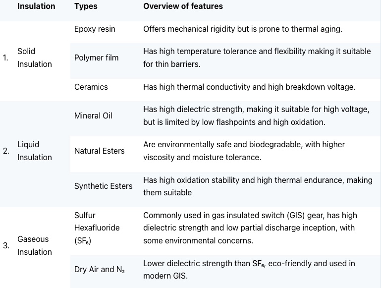
Table 1. Table showing the different HVDC insulation choices with an overview of their features.
Partial Discharge Management and Aging
For reliable insulation and to prevent premature aging, PD must be avoided. A safe design of an MT-HVDC system is ensured by a peak operating voltage that is lower than the minimum voltage at which PD occurs. This PD inception voltage (PDIV) is evaluated by considering the insulation thickness (d) and the critical electric field strength (Ecrit).
$$\text{PDIV} = E_{crit} \cdot d$$
Each PD event releases energy and damages the surrounding dielectric material through localized heat generation. Other than heat, PD also facilitates oxidation and chemical degradation of polymer chains, triggering reactions that change the composition of the insulation material.
In MT-HVDC systems, IEC 60270 provides PD test standards for measurement and classification of partial discharge activities, and facilitation of factory acceptance testing during PDIV verification. Additionally, factors like inclusion, voids, and sharp edges of electrodes must be taken into account as they can greatly lower the effective insulation strength.
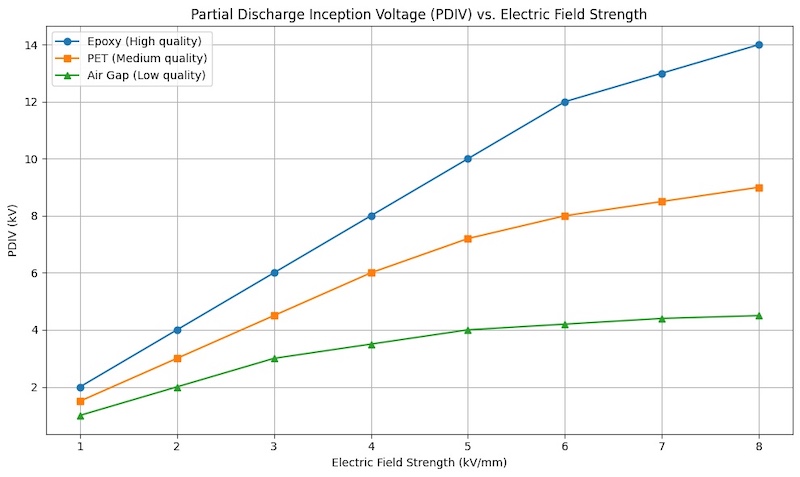
Figure 2. Insulation materials with a higher PDIV at the same electric field strength show greater resistance to degradation. Image used courtesy of Bob Odhiambo.
When it comes to life expectancy modelling of insulation material, the aging process can be predicted by accounting for electric field stress with empirical models that relate the magnitude of the electrical stress and the expected lifetime, as shown in the formulation below.
The model accounts for how sensitive the insulation material is to the rate at which the electric field changes using an aging exponent (n). In the equation, the expected operational lifetime is given by (L), whereas (L0) represents the reference lifetime under a known reference field strength (E0).
$$L = L_0 \cdot \big( \frac{E_0}{E} \big)^n$$
Resilient Insulation for MT-HVDC Grids
With advancements in modern MT-HVDC systems and the adoption of modular multilevel converters (MMC) topologies, insulation design needs to go beyond dielectric strength; long-term insulation performance exceeding 30 years requires a combined approach of simulation, material science, and experimental monitoring. Insulation designs that are resistant to thermal oxidative degradation and comply with IEC standards are potential factors to aid engineers in insulation material selection for their HVDC grids, which maintain stability under transient voltages and varying environmental conditions.