Facebook
 Google
 GitHub
 Linkedin
Innovative Integrated Magnetics for Hybrid and Electrical Vehicles Onboard Battery Chargers
This article discusses the integration of insulating transformer and resonant chokes on the same core to lower the magnetics volume in ZVS or LLC converters.
How to lower the volume of magnetics in ZVS or LLC converters by integrating the insulating transformer and its resonant chokes together on the same core.
Introduction
Nowadays, the market of hybrid and electrical vehicles is growing quite fast. These are alternative solutions to common thermal engine cars to reduce the global pollution, especially in terms of rejected CO² or other NOx pollutants as well as toxic-for-health thin particles. Such new models require more and more power electronics inside, not only for the electrical motor supply with speed and torque control, but also for high-voltage battery chargers and stable in-car continuous low-voltage power supplies.

Figure 1: a. New SUV cars become plug-in hybrids too b. Trend in HEVs on 2013-2024
For 200-450V battery chargers, different power electronic topologies like quasi- or resonant half- or full-bridge can be used. They enable the development of high-efficiency converters (> 90%) with a switching frequency commonly in the 70-350kHz range. A power of 3.5kW enables a complete charge of the batteries during one night (around 6-8 hours through a 10/16Arms domestic plug) whereas 7kW reduces the duration to approx half-a-day charging (32Arms plug).
The power can be increased from 11-22kW (AC 3-phase network) to 50kW (DC network) for ultra-fast charging in 30-60 minutes but it requires dedicated charging stations to be installed through the cities. For modularity concept, 3.5kW bricks can be connected together with the selection of 1-phase 3.5 or 7kW or 3-phase 11kW charging configurations.
Thus 3-4kW HF transformers are required in the charging operation both for voltage level adaptation from the rectified mains to the battery voltage and for the by circuits physical separation between the AC and DC. As the component belongs to a switch-mode power supply it is often associated to inductors for benefit in soft-switching, better control and EMI reduction.

Figure 2: Common battery charger SMPS schematics
LLC topology
The first possible and most efficient used topology is the LLC resonant bridge. It can be formed from 2 switching transistors (half-bridge structure, figure 3) to 4 transistors (full-bridge operation). The transistors in series form legs connected to the DC-bus (input voltage Uin). The transformer and its related resonant tank are connected between these legs. At the secondary side we find a rectifier module made of 2 (center-tap transformer) or 4 diodes (single secondary winding transformer) and a filtering capacitor.
The resonant tank associates to the transformer a parallel inductor (Lp) and a serial additional inductor (Lr) as well as a serial capacitor (Cr). These 3 passive components are usually discrete components that require space in the application. They can show losses and possible related heating at additional costs. The idea here is to integrate the Lp and Lr components inside a single magnetic set around the transformer. The set of values is defined to fix the operating frequency range according to the Uout/Uin ratio to achieve. The turn-ratio of the transformer is another parameter linked to the resonant tank values. Example for a 3.5kW LLC full-bridge converter from 220-420Vdc to 200-450Vdc in the 70-200kHz range : Ns/Np = 1, Lp = 130µH, Lr = 22µH and Cr = 100nF (all at +/-5% tolerance).

Figure 3: Half-bridge resonant LLC converter topology
This resonant topology is preferred in kW battery charging devices since the control in power is only made by frequency adjustment. According to the required output voltage-current needs (following the batteries charging load-chart), the control-loop and associated microprocessor calculate the switching frequency to apply to have the corresponding Uout/Uin ratio. Even if the voltage that is applied to the transformer is of a symmetrical bipolar wave-shape, the current shows a quasi-sinusoidal waveform which is a great advantage for higher efficiency by soft switching as well as for EMI reduction.
ZVS topology
The second possible topology is the ZVS phase-shift full-bridge which is a quasi-resonant structure to also reduce the losses in the semiconductors at switching instants (figure 4). In this, the control of the transistor legs is shifted between both diagonal of MOSFET or IGBT transistors and the applied duty-cycle reflects the calculated compensation to get the required output voltage Vout at a given Vin point. The ZVS inductor in series with the transformer is used to create the zero-voltage-switching condition with the self-capacitance of each MOSFET transistor.

Figure 4: ZVS phase-shift full-bridge converter topology
Even if it is often requested to use the leakage inductance value of the transformer, this practice is not without any effect in the self-heating of the transformer. As a matter of fact, a value from 5 to 15µH is normally necessary to create the ZVS condition with MOSFETs showing some 1-5nF of parasitic capacitance value. It cannot correspond to the self leakage inductance of the transformer without a bad coupling (k < 0.995) which generally leads to additional high-frequency losses inside the windings which are crossed by the energy not stored inside the magnetic core. That’s why a discrete additional inductor in series with the primary of the transformer is normally found (figure 5).

Figure 5: ZVS transformer and its related serial resonant choke
In some cases it can be better to introduce also a thin gap in the transformer core to make its behavior more linear in case of any possible dissymmetry that can appear secondary side due to the rectifier bridge or any difference in the cabling length or contact resistance between the two polarities of the secondary. Thus the magnetizing inductance value of the transformer is of a slightly lower value but with a more accurate tolerance on it. Example for a 3.5kW ZVS phase-shift full-bridge converter at 100kHz : Lmag = 800µH+/-20%, Lzvs = 7µH+/-10%.
The integrated magnetic set
The idea is to focus on a magnetic set that provides all these alternatives at once in a single component. The main advantages are the size and weight reduction at a more competitive price. In terms of cost, one has to consider not only the cost reduction because one or two physical components less but also in terms of assembling process of the converter where less connections have to be made. Some interconnections can be also directly replaced by special techniques at the proposed magnetic set level.
Thus the result is a kind of magnetic set (figure 6) where we find a common transformer, showing or not an air-gap, and an additional choke in series with the primary winding. The magnetic core of both serial components is shared together at one side. The choke is the serial inductor Lr or Lzvs depending on the topology (LLC or ZVS). The transformer can include the Lp value if the center leg is cut to set the magnetizing inductance value at Lp.

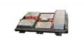
Figure 6: The magnetic set integrates both a transformer and a couple of resonant inductors
The use of low-losses high thermal stability ferrite cores as well as thin stranded and twisted conductors in parallel for the winding participate to the optimization of the losses versus temperature, input voltage range and current consumption according to the charging level of the battery.
The use of special isolated conductors is followed to fulfill the isolation and creepage distance as required by many electrical safety standards (UL-2202, IEC-61558…). As a matter of fact, the isolation requirements does not only include a high dielectric strength (typically 2.5-4kV) but also construction criteria like creepage distance, clearance and distance through the insulation to guarantee the reliability of the insulating system provided.
Conclusion
The size reduction of magnetic components embedded in battery chargers for the increasing demand of HEVs goes through the integration of the switching transformer and its associated resonant chokes on the same core while providing a reliable insulation and an efficient cooling capability. This 3-in-1 concept (1 transformer + up to 2 chokes) enables not only a volume and weight reduction but also a big cost saving because less materials and also a reduced connecting system (chokes and transformer partially linked internally) are used. The work is not finished at that point and PREMO R&D has been already developing an innovative 3DpowerTM concept which will soon enable to design more compact solutions for the benefit of automotive SMPS.
However, the new BCIM Series (Battery Chargers Integrated Magnetics) is already presented as available standard products from PREMO catalogue. PREMO is a Spain-based company engaged in the development, manufacture and sales of electronic components with a special focus on the growing market of HEV, smart metering and market segments including automotive, telecommunications and industrial electronics. Our product portfolio includes NFC and RFID antennas, power transformers, inductors and chokes, current sensors, EMC filters, PLC components and accessories. In addition to our broad range of standard components, off-the-shelf products, PREMO designs custom solutions to fit customer requirements.
This article originally appeared in the Bodo’s Power Systems magazine.
About the Author
Patrick Fouassier works as the Research and Design Manager at Premo Group, France. He is mainly responsible for the development and project management of innovative solutions for the automotive sector with components for battery chargers and DC/DC converters from some kW to tens of kW used in new electrical and hybrid cars. He earned his Bachelor's Degree in Electrical Engineering and his PhD in Electrical Engineering both at National School of Energy, Water and Environment (Grenoble INP - Ense3), one of the engineering schools of the National Polytechnic Institute of Grenoble.