Facebook
 Google
 GitHub
 Linkedin
Inductors: Energy Storage Applications and Safety Hazards
In this article, learn about how ideal and practical inductors store energy and what applications benefit from these inductor characteristics. Also, learn about the safety hazards associated with inductors and the steps that must be implemented to work safely with inductive circuits.
When an ideal inductor is connected to a voltage source with no internal resistance, Figure 1(a), the inductor voltage remains equal to the source voltage, E. In such cases, the current, I, flowing through the inductor keeps rising linearly, as shown in Figure 1(b). Also, the voltage source supplies the ideal inductor with electrical energy at the rate of p = E *I.
Without the internal resistance, the inductor is lossless because it cannot produce heat or light from the available energy. Therefore, all the energy supplied by the source ends up being stored in the generated magnetic field – exactly how energy is stored in rubber bands when stretched. The rising current causes more and more energy to be stored in the magnetic field due to the expansion of the magnetic lines of forces. The lack of a resistive element in the circuit means the current will continue to rise. In such an ideal scenario, the inductor has an infinite capacity and will continue to charge forever until the circuit is broken. The stored energy can be recalled at any time by breaking the circuit of Figure 1(a), causing a breakdown of the magnetic field and releasing its energy.
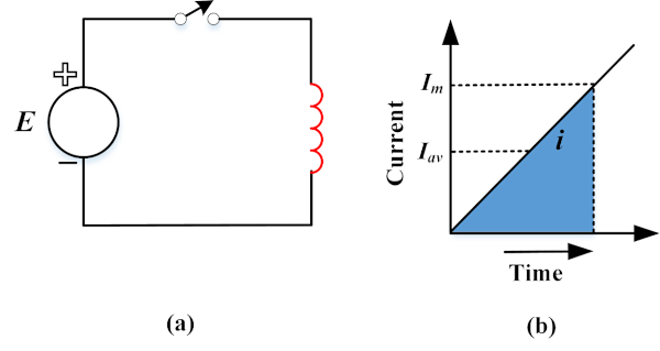
Figure 1. (a) Simple Inductor circuit. (b) Rising current profile. Image used courtesy of Amna Ahmad
In a purely resistive circuit, the voltage and current are not a function of time. Therefore, they do not change with time. In such circuits, the source transfers energy to the resistance equal to W = P *t = V *I *t.
However, in a purely inductive circuit, the current increases linearly with time, as the voltage remains constant for the circuit in Figure 1(a). This means there is a constant rate of change in the system's current. Therefore, the average current value, Iav, will be equal to Im / 2 as the current goes from zero to Im. And the resultant stored energy W will be equal to:
\[W=V\times\frac{1}{2}I_{m}\times t\]
And due to the constant rate of change of current, the inductor voltage will be equal to:
\[V=L\times\frac{di}{dt}=\frac{LI_{m}}{t}\]
By substituting the value of V in the equation for W, we get the total energy stored by the magnetic field of the inductor:
\[W=\frac{LI_{m}}{t}\times\frac{1}{2}I_{m}\times t \]
\(W=\frac{1}{2}LI^{2}_{m}\) (1)
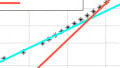
For a practical or a non-ideal inductor circuit, the internal resistance cannot be ignored because it plays an essential role in limiting the system current to an upper value of Im = E/R. In this circuit, the instantaneous current and voltage profiles are not linear or constant. They both vary with time and are continuously changing at a non-constant rate. Therefore, it is important to find the instantaneous values of the inductor voltage and current, v and i, respectively, to find the momentary rate of energy storage. Much like before, this can be found using the relationship p = V * i. Figure 2 shows the voltage and current profiles of the non-ideal inductor circuit and the subsequent energy profile.
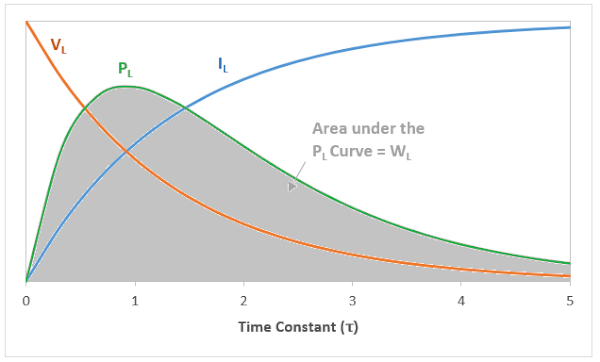
Figure 2. Voltage, current, and energy stored profiles for a practical inductor. Image used courtesy of Amna Ahmad
The inductor starts resisting the current flow and the magnetic field's formation, but as it increases, the magnetic field continues to expand. When the current gradually approaches its steady-state value Im and becomes constant, the magnetic field ceases to expand further. In this instance, the inductor voltage also falls to zero, indicating that the inductor now behaves like a short circuit that allows maximum current flow. Thus, the power delivered to the inductor p = v *i is also zero, which means that the rate of energy storage is zero as well. Therefore, the energy is only stored inside the inductor before its current reaches its maximum steady-state value, Im. After the current becomes constant, the energy within the magnetic becomes constant as well. Thus, the inductor takes no more energy, albeit its internal resistance does cause some losses as the current flows through it, such that Plosses= Im2R. These losses are unavoidable because the constant current flow is necessary to maintain the magnetic fields.
The energy within the magnetic field can be taken as a product of the average power and the elapsed time since switch closure. This is highlighted as the area under the power curve in Figure 2. The energy in the inductor can be found using the following equation:
\(w=\frac{1}{2}Li^{2}\) (2)
Where i is the current (amperes), L is inductance (Henry), and w is the stored energy (joules).
Applications of the Stored Energy in Inductors
Switched-mode power supplies (SMPS)
Switched-mode power supplies (SMPS) convert AC and DC supplies into the required regulated DC power to efficiently power devices like personal computers. An Inductor is used in SMPS because of its ability to oppose any change in its current flow with the help of the energy stored inside it. Thus, the energy-storage capabilities of an inductor are used in SMPS circuits to ensure no ripples in the SMPS output current.
The inductor subdues any output current fluctuations by changing its behavior between a load and a supply based on the SMPS current ripple. The inductor behaves like a load and stores energy to prevent ripples from producing excess current. It acts like a current supply when the ripple reduces the current value. In each case, the inductor prevents the ripples from influencing the regulated DC.
Buck Regulator
An inductor can be used in a buck regulator to function as an output current ripple filter and an energy conversion element. The dual functionality of the inductor can save the cost of using separate elements. But the inductor’s inductance value must be selected to perform both functions optimally. Large inductor values give low ripples and maximum power output. However, the value should not be too high because the inductors can get very bulky and provide a poor transient response.
Limiting Inrush Currents
Some AC/DC and DC/DC applications (motors, transformers, heaters, etc.) can cause high Inrush currents to flow in an electrical system. These currents are needed to produce charging effects and magnetic fields when these devices are initially energized. These high-value currents are a part of the system and must be tolerated for the first few cycles. However, the high current can cause overcurrent protection devices like fuses and relays to trip the circuit to protect converters and other equipment from failure. In such cases, an inductor can be added to limit the inrush current. Here, the inductors slow down current surges or spikes caused by the inrush current while still allowing the delivery of the inrush current to required applications.
Safety and Hazards
An inductor in an electrical circuit can have undesirable consequences if no safety considerations are implemented. Some common hazards related to the energy stored in inductors are as follows:
- When an inductive circuit is completed, the inductor begins storing energy in its magnetic fields. When the same circuit is broken, the energy in the magnetic field is quickly reconverted into electrical energy. This electrical energy appears as a high voltage around the circuit breakpoint, causing shock and arcs. An accidental shorting of the inductor element can also cause it to release its stored energy as a heavy current. Both of these conditions can damage the circuit or cause injuries to nearby people.
- The inductor is surrounded by its magnetic field. Therefore, it can attract other magnetic materials in its area of influence. If the magnetic material is part of nearby devices, these devices can suffer mechanical stress.
- Before the current through an inductor reaches a steady state, the magnetic field continues to be built up as the current keeps increasing. This magnetic field can be considered a time-varying field that can induce emf and eddy currents in nearby conductive materials. These currents can produce heat and form their own magnetic field that interacts with the source field and causes mechanical stress in the conductive element.
Considerations for Safe Operation of Inductive Circuits
Automatic Discharge
Automatic shorting devices like varistors and freewheeling diodes can be used to provide additional current paths when the excitation is interrupted. This way, a path is provided to the inductor to release its energy without forming arcs at the circuit break point.
Connections
When an excited inductor loses connection to the supply, it quickly breaks its magnetic fields and tries to continue the connection to the supply with the converted energy. This energy can cause destructive arcing around the point where the connection is lost. Thus, the connectivity of the circuit must be continuously observed.
Eddy Currents
Self-induction and mutual induction due to the inductor's magnetic field can cause eddy currents to flow in the body of the inductor and any nearby conductors. These are undesirable because they produce mechanical stress, heat, and energy losses. Therefore, considerable mechanical and electrical support should be provided to dissipate any stress or heat produced safely.
Verify De-energization
Another safety consideration is to verify the de-energized state of inductors. Any residual energy in inductors can cause sparks if the leads are abruptly disconnected.
The exponential characteristics of a practical inductor differ from the linear behavior of ideal inductors; both store energy similarly–by building up their magnetic fields. These magnetic fields have undesirable effects on the inductors and nearby conductors, causing several safety hazards. It is essential to mitigate these safety concerns by making appropriate considerations and implementing proper failsafe technologies.
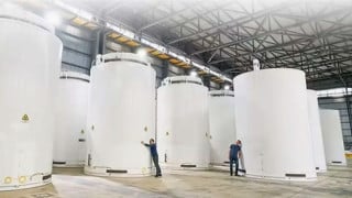
Featured imaged used courtesy of Adobe Stock
Related Content