Facebook
 Google
 GitHub
 Linkedin
How to Hack your AC/DC Converter – Part 2
How can you ‘hack’ something as basic as an AC/DC converter module? This article will use the example of a board-mounted power supply to demonstrate five possible AC/DC converter ‘hacks’ that could also be used for various other applications.
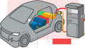
Let’s assume you have a power monitoring application in an electric vehicle (EV) charging application in which the auxiliary power supply needs to have multiple input options: three phase or single phase AC or high voltage DC or low voltage DC. Additionally, the charging application needs to be able to generate bipolar (±10V) output rail voltages to power the calibrated current and voltage sensors and amplifiers (Figure 1).
You check the manufacturer’s datasheets and find that a power supply with all of these particular input and output voltage combinations does not exist as a standard product. What can you do? You need to start hacking your AC/DC!
Hack #1: Use dropper diodes.
Low power AC/DC converters do not normally offer adjustable output voltages. The reason is simple: Unlike, say, an isolated 24-to-5V DC/DC converter, which might have a transformer with a 5:1 turns ratio, an equivalent AC/DC converter with 230VAC RMS input to 5V output will need a transformer with a 65:1 turns ratio. This is because the rectified AC voltage is significantly higher than the output voltage. The control loop in an AC/DC converter is optimised to compensate for a wide range of input voltages (typically 85-264VAC) and a fixed output voltage. If the output voltage was also made adjustable, the worst case input/output voltage combination combined with the high turns ratio could easily facilitate the converter operation to become unstable.

Figure 1. EV charging system with universal AC or DC supply. Image used courtesy of Bodo’s Power Systems
Evidently, it is possible to place positive and negative voltage LDO linear regulators on an AC/DC with ±12V outputs to regulate the voltages down to ±10V, but is there a cheaper and simpler hack?

Figure 2. Diode dropper. Image used courtesy of Bodo’s Power Systems
Silicon diodes have a typical 0.6V-0.7V forward voltage drop across them. Hence, three in series will drop 2.1V (Figure 2):
The heat dissipation in the diodes needs to be properly managed; for a 500mA output current, the power dissipation will be 350mW, so this requires suitably-rated diodes.
A similar solution can be applied on a single output AC/DC module to drop, say, a 15V output down to around 13.6-13.8V to trickle charge a 12V battery by inserting two diodes in series with the +Vout (Figure 3). Such trickle chargers are useful in applications, such as emergency lighting or fire alarms, which need to be normally mains powered but also need to operate independently without the AC supply.

Figure 3. Diode dropper battery trickle charger. Image used courtesy of Bodo’s Power Systems
Hack #2: Adjustable positive and negative output voltage rails
Negative voltage regulators are not cheap, and they require a bipolar output power supply. Is it possible to make a dual rail power supply with a single output AC/DC? This next hack will demonstrate how. Non-isolated switching regulators have the same basic function as linear regulators, and it has a several pin-compatible modules available (e.g. RECOM’s R-78 series). However, internally, they are very different. If the output of a switching regulator is tied to ground, the switching regulator GND pin is forced to go negative. The result is a positive-to-negative regulator (Figure 4).
Figure 3 shows a multiple output power supply (+12V, adjustable +1 to +10V and adjustable -1 to +-10V), which only uses three lowcost main components. The RAC05-12SK is a universal AC input (85VAC to 264VAC) 5W board-mount power supply, which despite having an only 1”x1” footprint, needs no external components. This is because the fuse and Class B EMI filter are all built in.

Figure 4. Adjustable bipolar (±) output rails from a single output AC/ DC converter. Image used courtesy of Bodo’s Power Systems
Two RPX-1.0 non-isolated SMD switching regulator modules are used to generate the adjustable output rails, one of which is used in the positive-to-negative configuration. The RPX-1.0 is a complete DC/DC power supply with integrated inductor. Although it can deliver an impressive 1A output current, the case size is only 5mm x 3mm with a low profile 1.6mm height. Therefore, the entire multi-output rail power supply could be built into a 1” x 1” board space by mounting the SMD components on the underside of the PCB next to the output pins (Figure 5).

Figure 5. Triple output AC/DC layout possibility with SMD components mounted on the underside of the PCB to keep within a 25.4 x 25.4mm (1” x 1”) overall footprint. Image used courtesy of Bodo’s Power Systems
Another advantage of using output side post-regulators is that the output voltages remain fixed even if the loads are highly asymmetric. A bipolar output AC/DC has two output voltages, but how do you regulate two opposing output voltages with only one feedback loop? There are two choices: Either you regulate the overall difference between the positive and negative output voltages and let the common pin (centre tap) of the output transformer float (Figure 6), or you only regulate the negative output and let the positive output float, or you regulate the positive output only and let the negative output float. However, if the output loading is very asymmetric, say, full load on one output rail and only 10% load on the other, then the output voltages will also be asymmetric (Table 1).

Figure 6. Asymmetric outputs with asymmetric loads (regulation across +ve and –ve outputs). Image used courtesy of Bodo’s Power Systems
| Regulation Method | Positive Load | Negative Load | Positive Voltage | Negative Voltage | Overall Voltage |
| Positive to Negative | 100% | 100% | +12V | -12V | 24V |
| 100% | 10% | +11V | -13V | 24V | |
| 10% | 100% | +13V | -11V | 24V | |
| Negative only | 100% | 100% | +12V | -12V | 24V |
| 100% | 10% | +11V | -12V | 23V | |
| 10% | 100% | +13V | -12V | 25V | |
| Positive only | 100% | 100% | +12V | -12V | 24V |
| 100% | 10% | +12V | -11V | 23V | |
| 10% | 100% | +12V | -13V | 25V |
Table 1. Comparison of bipolar regulation methods (typical values for ±12V nominal output). Regulated output shown in blue.
All of these regulation methods offer the same output voltages with balanced loads. However, there are differences among them if unbalanced loads are used. The advantage of regulating the combined output voltage is that the sum of the negative and positive rails remains fixed, but only regulating the positive or just the negative output offers less variation on that particular rail. There is no universal solution.
However, if switching regulators are used to post-regulate the outputs as shown in Figure 4, both the output voltages remain stable over all load combinations, even down to no load/full load conditions.
There is an additional advantage to using switching regulators on the outputs: They also deliver constant power. Lower the output voltage, the higher the output current. If, in the example of Figure 4, the regulated outputs were adjusted to ±3.3V, then, as long as the overall load was less than 5W, the maximum output current per rail that could be drawn would be up to 1.5A. This is much higher than the AC/DC’s nominal 416mA output current. It is useful because the majority of multi-rail applications need significantly more power on the one rail than on the others (main load + auxiliary loads), but this is not a problem when switching regulators are used. For example, in Figure 4, +12V @ 0.1A, +3.3V @ 1A and -3.3V @ -0.15A would be possible with all of the output voltages tightly regulated.

Figure 7. Typical output stage of an AC/DC converter. Image used courtesy of Bodo’s Power Systems
So far, we have only considered hacking the output of an AC/DC module, but what if we wanted to use alternative power sources? This is about Hack #3.
Hack #3: External DC supply on the AC/DC output
In a few specific field applications, it is necessary to be able to use either an AC or a DC battery supply, whichever is available. As it can be seen in Figure 7, if an external DC supply was connected to the output of a switched-off AC/DC converter, the output diode, Dout, would stop the external current flowing back through the output winding of the transformer.
However, the shunt regulator, IC1, would still be in-circuit. If the external voltage exceeded the set point of the shunt regulator, it would conduct and begin feeding the current through the optocoupler LED. As the AC/DC converter is inactive, there is no mechanism that would control this optocoupler current. Owing to this, the opto-LED could easily burn out. Therefore, placing an external voltage directly across the output of an AC/DC converter is not advisable.
Using two OR-ing diodes could be considered to steer whichever supply voltage is higher through to the application without letting the two supplies interacting with each other (Figure 8).

Figure 8. OR-ing diodes for an AC or an external DC supply. Image used courtesy of Bodo’s Power Systems
However, this hack, although simple, suffers from two big disadvantages. Firstly, the output voltage is always one diode drop lower than the supply voltage. Secondly, with higher current loads, the power dissipation in the diodes becomes significant (in the example shown in Figure 8, 3.5W). This means that large, expensive power diodes would be required with possibly additional heatsinking. Furthermore, the power wasted in diode D2 would harm the battery lifetime.

Figure 9. OR-ing diodes for an AC or an external DC supply. Image used courtesy of Bodo’s Power Systems
A better hack would be to use an ideal-diode IC, for example, the LM71300 from Texas Instruments that has integrated FETs for a very compact solution (Figure 9). This solution has the added advantage: the battery is protected from a damaging deep discharge by the under voltage lockout (UVLO) feature and the application is protected from the high-surge current capability of the battery by the dVdt control. Additionally, the load current from both sources can be monitored using the Imon outputs.
Hack #4: AC Phase Redundancy
Up until now, the hacks have all been concerned with the output side. This is reasonable, considering that the AC mains is a hazardous voltage and should be treated with the greatest respect. However, returning to our EV charger specification mentioned in the introduction, it can, presumably, function with single phase, multi-phase or high voltage DC supplies. The following hack, consequently, concerns the input side.
The half-wave rectified three phase input circuit shown in Figure 10 will have a rectified DC voltage of approximately 1.17 x Vphase, or about 270V for a nominal 230V single phase voltage. This is extremely high for a standard 230V±10% input AC/DC converter, but acceptable for an AC/DC converter designed to operate with up to 277VAC (the phase-to-phase voltage for 115VAC supplies). The circuit shown in Figure 10 uses input fuses to protect the three phase supply if any of the diodes fail, and the metal oxide varistor (MOV) to absorb excessive voltage surges that could damage the converter. The MOV is optional, as the converter itself is internally fused, but it may be required under local wiring regulations. The input diodes must have a suitable reverse voltage rating.
If any of the three phases drops out, the converter will still function. So, this hack is especially useful for powering three phase monitoring applications and sounding an alert in the case of any individual phase failure.
The RECOM /277 series have an AC input voltage range of 85- 305VAC. Thus, any /277 type converters can be used in this configuration as long as a neutral connection is available.

Figure 10. Phase Redundancy using a half wave three-phase rectifier. Image used courtesy of Bodo’s Power Systems
If a neutral line is not available, the voltage between two phases (√3 x Vrms or around 400V for a 230V single phase voltage) is too high for many AC/DC converters unless they have been specially designed for such purposes, such as the /480 series, which have an AC input voltage range of 85-528VAC or a DC input voltage range of 120V-745VDC.
As mentioned in the introduction, this hack should be used with care, as hazardous voltages are involved. Additionally, safety regulations may require additional safeguards, such as wider creepage or clearance distances or enhanced insulation withstand voltage, which would make such a hack unacceptable. For example, any circuit that is hard-wired to the mains supply is required to meet the safety requirements for over-voltage category III or IV.
This leads us to the final hack: grounding the output of an AC/DC for safety.
Hack #5: Output grounding
As AC/DC converters are isolated, the low voltage DC output is floating (galvanically isolated) from the mains supply and can be used as either a positive or negative supply. For example, a common communications supply bus voltage is -48VDC and this can be supplied by any AC/DC with 48V or ±24V output by tying the +Vout pin to 0V and using the –Vout pin for the supply rail.
For some applications, it is either advantageous or unavoidable to ground one of the output pins. At first glance, this would seem a simple enough thing to do, much like the comms power supply application that was mentioned. However, the regulations intended for AC/DC power supplies are not just about safety; there are EMC considerations that also have to be taken into account. Any circulating or induced currents that flow through the insulation capacitance can cause interference, which can make the final application fail the EMC testing. Also, grounding the output is almost guaranteed to cause such an unintended current loop. For instance, for a Class B device, even a loop current of a few tens of micro-amps can push the test results outside of the limits.
The required hack to meet EMC limits with a grounded output is to fit an external line filter with a common mode choke (Figure 11).

Figure 11. Recommended input line filter when the output is grounded. Image used courtesy of Bodo’s Power Systems
The two Y-caps create a low impedance path for any circulating interference currents back to ground while the common mode choke (CMC) impedes common mode interference that occurs on both the VAC(L) and VAC(N) pins simultaneously. Consequently, these are not seen by the input filter of the AC/DC module. Finally, the X-cap across the input helps attenuate differential mode noise in combination with the leakage inductance of the CMC. The high ohmic resistor across Cx is optional and used to discharge the capacitor when the power is turned off (required by some safety standards). Pre-built AC line filters are available from many suppliers, including RECOM.
This article is the second part of a two-part series, the first being “How to hack your DC/DC converter” - Bodo’s Power systems 01/2022
Featured image used courtesy of Bodo’s Power Systems
This article originally appeared in Bodo’s Power Systems magazine.