Facebook
 Google
 GitHub
 Linkedin
Gate Drivers for SiC-MOSFET/IGBT Power Modules and Their Advantages
This article highlights Tamura Corporation Gate Drivers module which is the 2DMB series for SiCMOSFET/IGBT power modules that contains DC/DC converters.
In order to meet new requirements for miniaturization, low-loss, and high reliability of power converters, power semiconductors manufacturers are constantly trying to improve SiC MOSFET and IGBT technologies. Finding the best compromise to progress on all these characteristics is problematic, because they are antithetical, therefore the innovation pace is slow. SiC MOSFET and IGBT performances are not only dependent on improvement made on high-power transistors but also on all the components around them.
Power semiconductors Engineers are looking for any improved characteristic on power electronics components, even if they are small. Tamura Corporation understood how crucial this matter is and decided to heavily invest on gate driver characteristics, like its operating frequency, electrical characteristics or its size. Tamura Corporation gate driver will definitely help engineers to develop more reliable, more efficient and smaller power conversion devices.
Foreword
Power modules are used as power conversion main devices in a wide range of applications: renewable energies (such as wind or solar powers), automotive industry with low-carbon emission vehicles such as hybrid (HEV) and electric vehicles (EV), electric railways, industrial equipment with inverters and UPS, but also consumer fields with air conditioners.
We are currently observing two different development trends on power semiconductors:
- In current power modules, IGBT (Insulated Gate Bipolar Transistor) is the mainly used technology and their performances are improving with each new generation. We are still expecting improvements on this technology using new structure such as FS Trench or Super Junction.
- New Power modules using new generation materials such as SiC (Silicon Carbide) and GaN (Gallium Nitride), used for wide-bandgap semiconductors. SiC MOSFET are the trendiest power modules right now.
Despite technology differences, all power conversion companies have a common goal: create the most energy-efficient system. Therefore, miniaturization and energy loss reduction are crucial parameters in the development of a power module. Improvements in these fields have impacts on how gate drivers should be designed: For example, we know that the impedance inside power semiconductors will increase, therefore a key parameter on how gate driver must be designed is their capacity to compensate this increase by lowering their internal impedance.
TAMURA has developed new Gate Driver modules (2DMB Series) that optimally drive latest generations of IGBT and SiC MOSFET power modules.
Product line up
Figure 1 shows TAMURA new gate driver module (2DMB series). This module contains DC/DC converters using planar transformer technology and gate controllers. This low-profile device provides galvanic isolation and two outputs in order to drive two power modules.
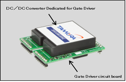
Figure 1: External view of 2DMB series
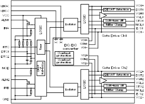
Figure 2: Block diagram of 2DMB series
A schematic diagram of the 2DMB series is shown in Figure 2. Our Electrical engineers have designed a reliable device containing several protective functions, such as DESAT detection, Soft Turn OFF and Miller Clamp functions.
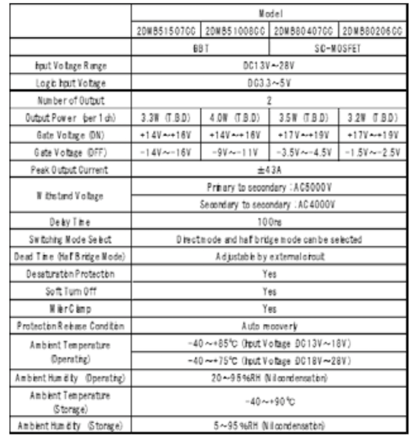
Chart 1: Spec of 2DMB series
The main specifications of our 2DMB models are shown in Chart 1. IGBT and SiC-MOSFET technologies are using different ±output voltages so we have developed two models supporting each technology. As our DC/DC converter has an output stabilizing function, it can support a wide-range input voltage (DC13 to 28V), instead of the usual restrictive DC15V.
Switching performance
Figure 3 shows a switching evaluation circuit where switching performance were evaluated with a pulse test on a 1200V / 600A IGBT. Figure 4 shows Vce, Ic, and VgeL waveforms. 600V is applied
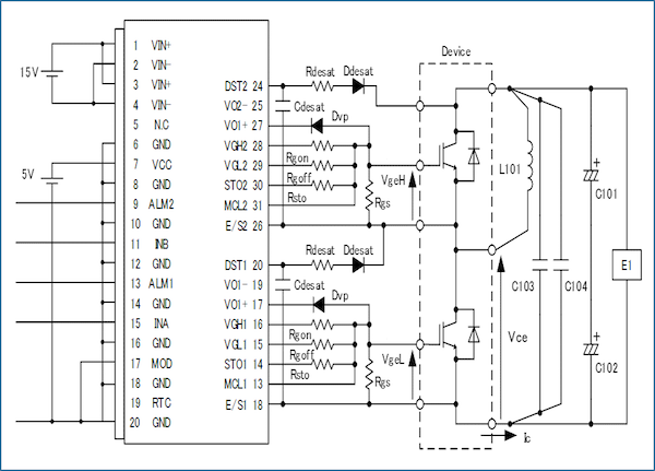
Figure 3: Evaluation circuit of Switching characteristic
(E1) and Ic is set to be 1200A which is twice the rated current. Gate resistances values have been minimized on purpose ( and ) to clearly observe behavior, shown in Figure 5 (Turn-ON Waveform) and Figure 6 (Turn-OFF Waveform).
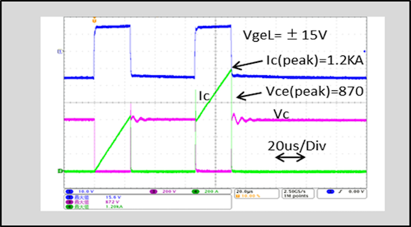
Figure 4: Pulse test (Wave form of Vce, Ice, VgeL)
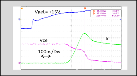
Figure 5: Turn-ON wave form (Vce, Ice, VgeL),
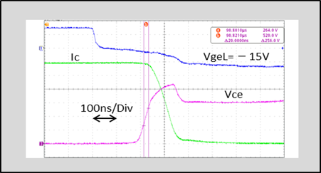
Figure 6: Turn-OFF wave form (Vce, Ice, VgeL)
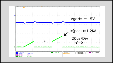
Figure 7: Wave form of High-side gate
The low impedance of TAMURA gate driver eliminates usual large swings in the waveforms of Vce, Ic, and VgeL. Another important pa-rameter that makes TAMURA gate driver highly reliable is its low stray capacitance (12pF): Turning OFF IGBT creates a noise proportional to the stray capacitance and to . Therefore, a risk of malfunction (high & low side simultaneously ON) may happen if that noise is too high. Figure 7 is a waveform demonstrating that switching noise on the low side does not affect the gate voltage on the high side (). The low stray capacitance makes TAMURA gate driver suitable for SiC MOSFET power modules that are operating at a higher frequency and is also suitable for 1700V IGBT (higher in both cases).
Drive system
Mechanically, gate drivers are usually installed very close to power modules or inductors which are challenging environments because of high temperature, magnetic noise and high voltage. In order to ensure reliability in such severe environments, TAMURA has equipped its new gate drivers with a capacitive isolation system. This insulation method, compared to photocoupler insulation, has several benefits:
-
Longer lifetime with lower aging effect
-
Lower breakdown field value
-
Higher Common Mode Transient Voltage (CMTI)
-
Shorter propagation delay time
-
Rise and fall times are almost the same
-
Less susceptible to magnetic noise
Switching time performance (90ns) example is shown in Figure 8 making power dissipation very low.
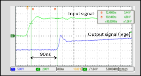
Figure 8: Transmission delay time
In case of power modules connected in parallel, the switching time variability is also an important factor to consider: if the switching time varies a lot between parallel modules, the global system is exposed to two major reliability risks, concentration of energy loss (heat) in one module and functioning outside of the safe operating area (SOA). TAMURA 2DMB series gate drivers have switching time variation as small ±5 ns which eliminates above stated risks.
Output performance
Figure 9 shows a block diagram of the DC/DC converter section of the 2DMB gate driver module. The output voltage is stabilized by an internal regulation circuit. Even when the input voltage (VIN) fluctuates, gate voltages (V01 and V02) can be kept stable. A stable output from gate drivers is a key function when driving SiC MOSFET power modules because the gate voltage window is extremely narrow (voltage as high as possible without exceeding the absolute maximum rating Vgss).
A new trend on high power facility market has emerged: using power modules with parallel connections to reach higher current. As a result, power modules makers have developed packages mechanically suitable for parallel connections. TAMURA has designed the 2DMB series to drive several power modules connected in parallel using only one gate driver. It simplifies drastically the overall complexity of the system.
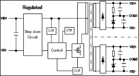
Figure 9: Block diagram of the DC/DC converter section
When power modules are connected in parallel, the electric charge amount coming from the single gate driver must be several times higher to turn on all power modules, hence a large peak current is required.
In order to reduce the switching energy loss, the gate resistance value must be set as small as possible and the current peak value must be increased to shorten the charging / discharging time.
In some cases, the external gate resistance is even set to 0Ω with a gate current only limited by the internal gate resistance of the power module.
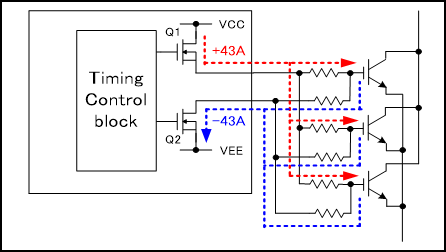
Figure 10: Block diagram of the IGBT parallel connection
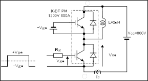
Figure 11: Diagram of short circuit test
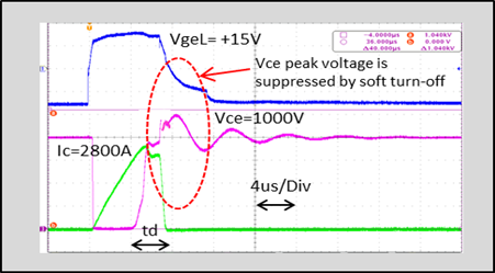
Figure 12: Wave form of short circuit test
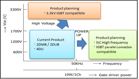
Figure 13: Development trend
A block diagram of IGBTs mounted with parallel connections is shown in Figure 10. The internal output buffer transistors (Q1, Q2) are chosen to generate a large peak current. As a result, the peak specification value of the gate current has been increased to ±43 A.
Short circuit protection
A short-circuit protection function is required to prevent from power module breakdown (in the event of a short circuit in the system). Short-circuit protections are realized through a DESAT diodes that detects rising points of Vce or Vds (respectively for IGBT or SiC MOSFET). When a short-circuit condition is detected, a large surge occurs in Vce (or Vds) due to inductances in the systems and in the power module. To dissipate this surge, TAMURA gate drivers are using a soft turn OFF function that is redirecting the detected surge to another gate resistance with impedance several times higher than the usual gate resistance (that has by default a low impedance to reduce losses)
TAMURA gate drivers 2DUB series provide two optional functions: soft turn OFF & an active clamping function. Both should be used if inductance of the system is high.The electrical short-circuit test diagram is shown in Figure 11 and equivalent waveforms are shown in Figure 12. The delay time (td) is a wait time in order to prevent the voltage output from stopping abruptly. The delay time is set to about 4μs, but this feature is adjustable.
Development trend
In the coming years, TAMURA will continue to develop new products such as:
-
Gate drivers compatible with high-frequency and high-current SiC MOSFET power modules
-
Gate drivers with enough output power to drive several power modules in parallel
-
High breakdown voltage gate driver compatible with 3.3KV power module.
About the Author
Hirotoshi Aoki works at the Unit Division at Tamura Corporation.
This article originally appeared in the Bodo’s Power Systems magazine.