Facebook
 Google
 GitHub
 Linkedin
Eliminating Power Conversion Trade-Offs by Moving to 1700V SiC MOSFETs
Designers of high-voltage power systems have struggled to meet customers’ needs for continued innovation when using silicon MOSFETs and IGBTs. The desired reliability is often not possible without sacrificing efficiency, nor can silicon-based solutions meet today’s challenging size, weight and cost requirements. With the arrival of high-voltage silicon carbide (SiC) MOSFETs, however, designers now have an opportunity to improve performance while solving all the other challenges.
Today’s 1700 V SiC products build on the success of SiC power devices rated from 650 V to 1200 V that have seen growing adoption over the past 20 years. The technology has already enabled significant advancements to end equipment; and now, with power devices rated at 1700 V, it is extending SiC technology’s myriad benefits into new end market segments, including electrified commercial and heavy-duty vehicles, light rail traction and auxiliary power, renewable energy, industrial drives, and more. Designers can maximize the benefits offered by 1700 V SiC MOSFETs with the right power packaging and proper gate driving. This increases their advantages over the incumbent silicon solutions across the widest possible range of power levels.
Benefits at Lower Power Levels
The benefits of 1700 V SiC MOSFET transistors begin at power levels as low as tens to hundreds of watts. SiC technology is the ideal solution for the auxiliary power supply (AuxPS) that is used in virtually every power electronics system Without an AuxPS, there is no way to get power to gate drivers, sensing and control circuits, or cooling fans. Because of its mission-critical functions, reliability is the top priority for AuxPS applications.
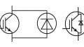
One of the ways 1700 V SiC MOSFETs help mitigate AuxPS failures is through their high breakdown voltage, lower specific on-resistance, and fast switching speed. Together, these attributes enable a more simplified circuit design using the single-switch flyback topology (see figure 1). In comparison, silicon-based solutions either have too low a voltage rating for this topology (which necessitates a two-switch architecture and doubles failure risk), or they sacrifice performance for voltage rating. They also are not available from enough suppliers and are more expensive than SiC devices.
By enabling the single-switch flyback topology, 1700 V SiC MOSFETs make it easier for today’s low-power, isolated, switch-mode power supplies to support diverse input and output requirements. They can accept a wide-ranging, high-voltage dc input (300 V to 1000 V) and output a low-voltage (5 V to 48 V) source. The single-switch flyback topology improves simplicity while reducing component count and associated overall cost.

Figure 1. The ubiquitous auxiliary power supply is shown above, using the wide input single-switch flyback topology. Image used courtesy of Bodo’s Power Systems
Beyond their improved reliability, less complex control scheme, reduced component count and lower cost, an AuxPS utilizing 1700 V SiC MOSFETs can also be more compact. The area-normalized onstate resistance, also called specific on-resistance (Ron,sp), of SiC MOSFETs is a fraction of what silicon MOSFETs exhibit. This means smaller packages may be used for the smaller die, and conduction losses are reduced which can ultimately result in reducing (or eliminating!) the size and expense of heat sinks. SiC MOSFETs also have lower switching losses, providing an avenue for shrinking transformer size, weight, and cost by increasing the switching frequency.
Figure 2 shows the degree to which various available SiC devices improve efficiency vs. output power. With today’s most efficient devices, it is even possible for system designers to implement passive cooling, i.e., no heat sink is required.

Figure 2. Comparison of efficiency vs. output power for multiple SiC options and one silicon high-voltage MOS device. Image used courtesy of Bodo’s Power Systems
Benefits Grow as Processed Power Increases
The impact of SiC technology’s faster, more efficient switching increases as the processed power increases. Move up the power scale to tens or hundreds of kilowatts (kW), there are many applications for SiC technology. Figure 3 shows a multi-kW three-phase inverter (75 kW in this example) and its topology. It can be found in EV traction, EV chargers, solar inverters, UPS, motor drives and more.
Figure 4 compares the efficiency of this inverter design using 1700V power modules in a low-inductance package to that of alternative power semiconductors. The SiC module demonstrated a peak efficiency of 99.4% at 10 kHz. Even when the switching frequency was tripled to 30 kHz, the SiC module still offered higher efficiency than the silicon IGBTs. This makes it possible to shrink heavy, expensive filter components to just one-third their original size.
In general, MOSFETs reduce switching losses by an average of 80% as compared to the silicon IGBT, which enables converters to increase switching frequency while reducing the size, weight, and cost of bulky, expensive transformers. The conduction losses of SiC MOSFETs and silicon IGBTs are similar under heavy loads, but it is more important to consider so-called “light-load” conditions under which many applications spend most of their service lifetimes operating. These include solar inverters located under a shade structure or on cloudy days; wind turbine converters operating on still days; and train doors that are only periodically opened/closed by transportation auxiliary power units (APUs). SiC MOSFETs reduce conduction losses compared to silicon IGBTs in these use cases, which complements their reduced switching losses. The combination of lower conduction and switching losses enables designers to reduce or eliminate heat sinking or other thermal management measures.
As with lower-power AuxPS applications, SiC MOSFETs used in this higher power range improve reliability by empowering designers to use a more simplified circuit topology and control scheme. This, in turn, reduces component count and associated costs. In these applications, the higher-power delivery needs of medium-power converters requires the use of a higher dc bus voltage, typically between 1000V and 1300V. To maximize efficiency, designers using silicon transistors at these high dc link voltages have traditionally had to choose from among a few complex, three-level circuit architectures. Examples include the diode neutral point clamped (NPC) circuit, the active NPC (ANPC) circuit and the T-type circuit. This changes with 1700V SiC MOSFETs, which allow designers to use the two-level circuit with half the device count and significantly more streamlined control. As an example, a system that previously used silicon IGBTs in a three-level circuit topology could use half (or fewer) 1700 V SiC MOSFET modules in a more reliable two-level topology.
Figure 5 shows the dramatic extent to which designers can reduce total part count for NPC, ANPC and T-type circuits with SiC technology. Without even considering the benefits of multiple parts being connected in parallel at each switch position, the various circuit architectures used with IGBTs have 4 to 6 times more components than a SiC solution. As the part count is decimated, so, too, is the gate driver count, and the control scheme is simplified.
Moving to Megawatt-Scale Applications
Megawatt-scale applications range from solid-state transformers (SSTs) and medium-voltage dc distribution systems to traction power units (TPUs) in commercial and heavy-duty vehicles. Other applications include central solar inverters and offshore wind converters, as well as shipboard power conversion systems. Figure 6 provides an example of a modular multi-level converter.
In applications within this multi-megawatt power range, a converter for a solid-state transformer as shown above uses multiple levels of series-connected power cells to meet voltage requirements. Each cell could be a half-bridge or a full-bridge cell. Some designers even opt for three-level architectures. Using modular solutions based on a basic unit cell improves scalability while minimizing maintenance. These unit cells, sometimes referred to as power electronic building blocks or sub-modules, are configured as cascade H-bridge converters or modular multi-level converters (MMCs).
To implement these unit cells, designers historically have used 1200 V to 1700 V silicon IGBTs. When they are replaced by 1700 V SiC MOSFETs at the unit cell level, there is the same effect as described in lower-power applications: better power handling capability and electrical performance. The lower switching losses of 1700 V SiC MOSFETs enable switching frequency to be increased. The size of each unit cell is dramatically reduced, and the high blocking voltage of 1700 V reduces the number of unit cells required for the same dc link voltage. This ultimately increases system reliability through the reduced cell count while reducing cost by using fewer active switches and gate drivers. As an example, when a 1700 V SiC solution is used in a solid-state transformer operating on a 10 kV medium-voltage distribution line, the number of series-connected cells can be reduced by 30 percent as compared to those using silicon alternatives.

Figure 3. In order, the key priorities for the multi-kW three-phase inverter shown above (including functional sections and topology) are efficiency, reliability, and power density (size and weight reduction). Image used courtesy of Bodo’s Power Systems

Figure 4. The efficiency of SiC solutions is compared to that of silicon IGBTs at 10 kHz and 30 kHz switching frequencies. Image used courtesy of Bodo’s Power Systems

Figure 5. SiC technology increases efficiency and power density while enhancing reliability through the ability to use simpler two-level topologies. This enables a 75 kW three-phase inverter to be built with as few as two parts per phase leg plus two drivers, as shown in the NPC, ANPC and T-type circuit examples above. Image used courtesy of Bodo’s Power Systems

Figure 6. Modular multi-level converter. Image used courtesy of Bodo’s Power Systems
Importance of Power Packaging and Proper Gate Driving
Because SiC MOSFETs can switch high levels of power at very high speeds, there are secondary effects that must be mitigated, including noise and electromagnetic interference (EMI), as well as limited short circuit withstand time and overvoltage caused by parasitic inductance and overheating. The typical medium-power converter turns off hundreds of amperes across a 1000 V – 1300 V bus in under a microsecond.

Figure 7. Designers have many package options with today’s SiC modules, including half-bridge options with stray inductance as low as < 2.9 nH as shown above. Image used courtesy of Bodo’s Power Systems
Microchip has SiC MOSFET module packaging options available that significantly reduce parasitic inductance. These include half-bridge packages with as little as < 2.9 nanohenry (nH) of stray parasitic inductance, which maximizes current, switching frequency and efficiency (see figure 7). These types of packages also offer higher power density and a compact form factor, enabling lower quantity of modules in parallel to achieve complete systems, which helps to further downsize equipment.
In addition to minimizing package inductance and optimizing system layout, designers also can use a new method of gate driving designed specifically to mitigate the secondary effects of SiC MOSFETs’ faster switching speeds. Today’s configurable, intelligent, and fast-acting digital gate drivers cut drain-source voltage (VDS) overshoots by up to 80 percent as compared to the traditional analog approach and reduce switching losses by up to 50 percent. They also cut time to market by up to six months and provide new augmented switching capabilities.
These capabilities enable designers to explore configurations and re-using them for different gate driver parameters such as gate switching profiles, system-critical monitors, and controller interface settings. They can quickly fine-tune gate drivers to support many different applications without making any hardware modifications, reducing development time from evaluation through production. They also can change control parameters throughout the design process, and change switching profiles in the field as required and/ or if/when SiC MOSFETs degrade.
Today’s SiC MOSFET offerings should also be part of a comprehensive SiC ecosystem that provides a direct path from evaluation to production. This includes customizable module options as well as digital gate drivers that allow users to optimize system performance and reduce time to market with the click of a mouse. Other ecosystem elements should include reference module adapter boards, an SP6LI low-inductance power module, mounting hardware and connectors to the thermistor and DC voltage, plus a programming kit for the configurable software. Companion discrete products round out the ecosystem.
A Continuum of Benefits
Across a continuum of power conversion applications, from watts to megawatts, high-voltage SiC MOSFETs are moving designers beyond the compromises of silicon solutions to drive innovation in power conversion system development. They increase reliability while reducing cost and simultaneously shrink the size and weight of more efficient power converters and power systems. When used with intelligent digital gate driving, 1700V SiC MOSFETs deliver their greatest possible value. Microchip offers a broad portfolio of rugged and reliable SiC components in the form of die, discretes and power modules, as well as digital gate driver solutions, that allow the designer to adopt SiC with ease, speed, and confidence.
This article originally appeared in Bodo’s Power Systems magazine.