Facebook
 Google
 GitHub
 Linkedin
DC/DC Converters Optimized for Energy Storage Elements in Smart Grid Solutions
DC/DC converters are a core element in renewable energy production and storage unit management. Putting numerous demands in terms of reliability and safety, their design is a challenging task of fulfilling many competing requirements. In this article, we are on the quest of a solution that combines answers to these questions in one single device.
The energy transition is on the rise. The proportion of renewable energy sources such as wind power or photovoltaic energy is growing. On the opposite, stable electric power supply and availability have to be guaranteed at any time. This undeniable fact raises the question of energy storage in future decentralized energy systems. Storing energy in the form of current or voltage means to use higher voltage levels in order to benefit from higher efficiency. Therefore, powerful DC/DC converters are needed for bringing the voltage down to another level, in order to provide auxiliary voltages for control electronics (figure 1). On the other hand, the way towards a smart grid, that is able to retrieve energy when needed, calls for availability round the clock. Monitoring features, control unit functions, and communication modules with energy supply companies have to work reliably, for the energy storage elements as well as for the primary energy production itself: As an example, a wind turbine, producing voltages up to 3000 V, needs an underlying supply voltage to be set in motion at all. So DC/DC converters will be found anywhere in the countryside.
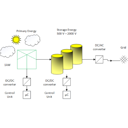
Figure 1. DC/DC converters in application. Image used courtesy of Bodo's Power Systems magazine.
High requirements guarantee maximum grid stability
DC/DC converters are largely used in today’s electric devices, they are indispensable in the use of household or entertainment appliances. However, in most cases, these devices are designed for the use in low voltage range. They usually convert down from line voltage level to 5V, 15V, or 24V. Hence, they are conceived for this specific operating condition. They have to take into account a number of constraints that concern insolation, cooling, and reliability issues. Given their limited input range, these challenges are easy to be dealt with.
But considering now use for MVDC (medium voltage DC) applications, as is the case for energy storage elements or renewable energy plants, the requirements are increasing. For safety reasons, insulation gains in importance as the input voltage might go up to 1000V, 2000V, or even higher for some use cases. On the opposite, the higher the voltage, the more difficult is the process to guarantee an insolation proof construction of the material in use. In addition, given the importance of supply security in the energy grid, a maximum of reliability is required. Considering the very complex interdependences of today’s energy grids, the failure of such a DC/ DC module, integrated anywhere in the supply line, can cause the breakdown of the whole system with all negative consequences for consumers. In conclusion, confident solutions to limit EMC impact and to ensure galvanic separation have to be found. Nevertheless, the operating conditions of such devices are far to be comparable to those applied to conventional DC/DC converters, like flyback converters conceived for low voltage context. Renewable energy is caught there where local conditions are most favorable, like on mountains or other areas where extreme conditions are prevailing. Hence, high altitude, corrosive impact, and inconvenient temperature have to be taken into account. On the other hand, efficiency issues have high priority. So what would this mean for such an MVDC application under real conditions?
On the track of parasitic elements
Following the logic that higher voltages are beneficent to energy storage applications as energy is growing proportionally to voltage squared, let us look at a small example concerning the DC/DC conversion mentioned above. We take the equation W = 1/2 x C x U2 as a basis. However, in real life applications, power losses during the transformation cannot be avoided. Voltage drop regulation is no longer option in most cases. Consequently, the voltage will be clocked to transfer the power from primary to secondary side in order to limit these losses. Anyway, parasitic elements come to disturb the efficiency of such an application, as the distances between primary and secondary side will be increased. Parasitic elements can be found all over the process that leads to the DC/DC conversion. There is a certain number of additional elements that make their contribution, as the transistor, the heatsink, the transformer itself, and the diode:
\[C_{par}=C_{OSS}+C_{Heatsink}+C_{Transformer}+C_{Diodereflect}\cdot\]
Considering this for a typical Fly Back converter, we have to accept that the parasitic capacity recharges when the transistor is switching through for a moment. When switching over the transistor due to clocking, the capacitor will discharge by a short circuit and heat will be released. Let us see what will be the differences in use between the DC/DC converter conceived for low voltage application and the one designed for MVDC context.
Power losses reaching a higher dimension
We take as an example a parasitic capacity Cpar= 250 pF for a very first estimation and a switching frequency fsw = 60 kHz. For the low voltage case, we assume an input voltage Vin = 110 V, an output voltage Vout = 25 V (24 V + VDiode = 24 V + 0.7 V ≈ 25 V) and a duty Cycle DC = 0.5. Out of that, we can first calculate the turns ratio needed for holding the energy balance inside the transformer and then the drain voltage VDS of the transistor:
\[\frac{V_{in}\times t_{on}}{n_{prim}}=\frac{V_{out}\times t_{off}}{n_{sec}}\Rightarrow \frac{n_{prim}}{n_{sec}}=\frac{V_{in}\times t_{on}}{V_{out}\times t_{off}}\]
\[t=\frac{1}{f}\]
\[t=\frac{1}{60kHz}=16\mu s\]
\[t_{on}=t_{off}=0.5\times t=8\mu s\]
\[\frac{n_{prim}}{n_{sec}}=\frac{110V\times 0.08 ms}{25\times 0.08 ms}= 4.4\]
\[V_{DS}=V_{in}+\frac{n_{prim}}{n_{sec}}\times V_{out}\]
\[V_{DS}=110V+4.4\times 25V=220V\]
Concerning the power losses, we get already an idea of what will be the switching losses caused by the parasitic elements:
\[P_{loss,par}=\frac{1}{2}\times C\times U^{2}\times \frac{1}{t}\]
\[P_{loss,par}=\frac{1}{2}\times 250pF\times(220V)^{2}\times\frac{1}{16\mu s}\approx 0.36W\]
Speaking for an output power of 250 W, this will only be about 0.15%. So they seem to be negligible at a first glance. In comparison, transistor conduction losses, caused by the inner resistance of the transistor when switched on, will matter to a larger extend. As an example, we will consider an effective current ÎTrs = 9 A for a TO-220 600 V transistor with a switch-on resistance Rds,on = 0.1 Ω @ + 100 °C:
\[P_{loss,con}=Î^{2}\times\frac{DC}{3}\times R_{DS,on}\times\frac{1}{t}\]
\[P_{loss,con}=(9 A)^{2}\times\frac{0.5}{3}\times 0.1\Omega\times\frac{1}{16 \mu s}=1.35W\]
So this will be about 0.55% of the output power and almost four times the power losses caused by parasitic elements. However, considering now a medium high voltage system with an input voltage Vin = 1000 V, we can see that power losses matter to a very larger extend:
\[\frac{n_{prim}}{n_{sec}}=\frac{1000V \times 0.08ms}{25\times 0.008}= 40\]
\[V_{DS}=1000V+40\times 25V=2000V\]
\[P_{loss,par}=\frac{1}{2}\times 250pF\times(2000V)^{2}\times\frac{1}{16 \mu s}\approx 30W\]
As we can see, this makes already 12% of the output power. Hence, the flyback converter is unfavorable in this particular application because the reflected voltage will be added and worsen the parasitic effect. The first step towards minimizing these undesired effects will be the use of another circuit design.
Optimizing losses by circuit design
Let us look now at other types of converters. Using for example a forward converter instead of the flyback is a possibility. This structure will follow a different principle because of using a current storage choke (L).
\[V_{S}-V_{out}-V_{L}=0\]
\[V_{out}-V_{L}\]
\[V_{in}\times\frac{N_{sec}}{N_{prim}}=V_{out}\times\frac{T}{t_{on}}=V_{S}\]
\[V_{in}=V_{out}\times\frac{N_{prim}}{N_{sec}}\times\frac{1}{DC}\]
Despite this, using a simple forward converter would bring along other disadvantages in terms of efficiency. Using a bridge topology will be another possible step of optimizing circuit design. This choice will also admit using a push-pull converter with extended performance range. Using the full bridge topology (figure 2), we have to take into account that four transistors are necessary to realize the circuit, but we do not have the negative effect caused by the reflected voltage that we saw for the flyback converter:
\[P_{loss,par}=4\times\frac{1}{2}\times 250pF\times(1000V)^{2}\times\frac{1}{1.6 ms}\approx 30W\]
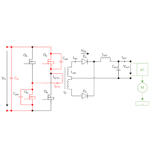
Figure 2. Full-bridge converter topology with midpoint circuit. Image used courtesy of Bodo's Power Systems magazine.
Passing over now to a half bridge topology, where only two transistors are used, we will realize that the losses are only half as high as in the previous design:
\[P_{loss,par}=2\times\frac{1}{2}\times 250pF\times(1000V)^{2}\times\frac{1}{16 \mu s}\approx 15 W\]
Nevertheless, referring to MVDC context, they still take a considerable part of the desired performance.
Following these examples, the power losses due to parasitic elements differ according to the topology in use, but they will in any case rise up to almost 6 -12% of the output power. As a result, reducing these parasitic elements has high priority in order to make the devices work in a more efficient way, but revising the circuit design is only one part of the answer. Another possibility would be reducing the switching frequency, but this comes along with limitation of the input voltage range and compromises in terms of component size. The same applies for optimizing the temperature stress, by adding elements as cooling fans and thicker aluminium heatsinks. In any case, for fulfilling the requirements in terms of reliability, EMC, or weatherproofing, a large number of additional modules have to be added as well: It has to be emphasized that it is not possible to apply standard components. Nevertheless, many DC/DC converter producers that enter the field of renewable energy solutions did not yet face these issues because they had been specialized in low voltage applications where the problem is not as crucial as that. So a potential energy supplier would first have to develop its own system by assembling the necessary elements one by one, in a long and development-intensive process.
An all-in-one solution based on experience
In contrast, Grau Elektronik offers products that already include solutions to these specific MVDC requirements. Therefore, its developers refer to MVDC applications already realized in the field of railroad technology. As the producer looks back on twenty years of experience in the field, a large number of solutions for contact wire converters have been developed. Projects with similar context are, for example, converters installed at gated rail crossings. Depending on the surrounding area, they might be placed under extreme conditions as well, for example in weather-exposed locations or at altitudes. Hence, answers to reliability, EMC, vibration, climatic, and heating issues are already implemented in the converter, so no need to add complementary elements as fuses, filters, or heatsinks. Input/output separation with galvanic insulated current paths fit for safety and critical noise sensitive applications. Analog and digital current and voltage control loops decouple and provide microcontrollers, cooling fans, electric valves, contactors, and sensors even in case of high fluctuations in supply voltage, load, and temperature. Specialized for railroad applications, the existing converters are designed for 24/7 use and high MTBF, completely maintenance-free (figures 3 and 4). The nominal usage time of the converters is stated LT (LifeTime) for > 25 years referenced to average temperature Tamb = + 40°C. MTBF value is about λ < 800 fit referenced to nominal output power and Tamb = + 40°C. The converters are designed for three different input voltage ranges, as shown in the table below. The standard output voltage is 24V, others are available on request.
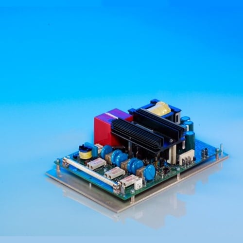
Figure 3. 250FDB 750 M24, a product developed for railroad technology. Image used courtesy of Bodo's Power Systems magazine.
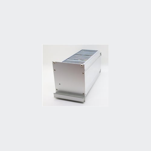
Figure 4. Sample product (250SWI 1000 M110). Image used courtesy of Bodo's Power Systems magazine.
| Power Range | Input Voltage Range | Output Voltage | Interfaces/ Signals |
| 75W | 200VDC – 1000VDC | 24V, 48V, 110V | Powerfail, Enable, LEDs |
| 800VDC – 2250VDC | |||
| 150W | 250VDC – 1000VDC | ||
| 800VDC – 2250VDC | |||
| 250W | 250VDC – 1000VDC | ||
| 1000VDC – 2100VDC | |||
| 500W | 500VDC – 1200VDC |
Tu: - 40°C … + 70°C
It has to be mentioned that even input voltages up to 4000 V would be feasible. During a model project accompanied in the US, Grau Elektronik has already gained experience: Equipping a wind turbine by a device converting down an input voltage of 3000 V, the company has proofed its role as a pioneer in the field.
Summary and Outlook
As our grid’s stability has highest priority, we realized how the use of DC/DC converters in renewable energy production and their storage applications puts heavy demands on the devices’ reliability. Having considered the transformation of MVDC and the operation under extreme environmental conditions, we saw the rise of problems that are very different from those applying to conventional DC/DC converters, conceived for low voltages. We became aware of the fact how insulation, galvanic separation, EMC, and thermal protection gained momentum. On the other hand, we discussed how increasing power losses threaten the efficiency of the process. Answers risk to be applied at the expense of component size and input voltage range. Standard components are far to be a solution to the requirements. Based on our experiences in railroad technology, we propose a device that includes all elements necessary for solving reliability, EMC, vibration, climatic, and heating issues.
As higher voltages have to be used all over the process, it becomes clear that not only the primary energy production has to be rebuilt, but also the energy storage modules, as well as distribution grids and compensation systems. In conclusion, the optimization of the existing infrastructure will be an overall task that requires proofed knowledge in medium and high voltage applications.
This article originally appeared in Bodo’s Power Systems magazine.