Facebook
 Google
 GitHub
 Linkedin
Damp-Oscillation Solution for Validation of the Nanocrystalline Core for Common Mode Choke
This article highlights Bs&T Frankfurt am Main GmbH damping-oscillation soluttion is presented with detailed principle description and technical discussion to address the challenges of nanocrystalline tape wound cores` validation
The increasing usage of rectification technology results in a significant increase of mutual electromagnetic interference. Usually RF input chokes, i.e. common mode chokes are used as a universal solution for the problem. The typical material for such applications is a variety of ferrites in the present.
And the high-permeable MnZn Ferrite material is preferred for conductive distortion while the low permeable material for radiation distortion. In the past decades the nanocrystalline tape wound core demonstrates its technological advantages, and already successfully replaces number of ferrite design, especially for high current applications, such as in motor drive, which is under harsh and high ambient temperature. Correspondingly, the design skill with nanocrystalline tape wound cores is well illustrated in VAC book [1].
Common-mode-cores are an effective measure to reduce commonmode-interference and they can be easily installed over the supplying cables of any drive system. The common-mode-current that flows through the parasitic capacitances of motor cables and motor housing can be reduced by using those cores significantly. The filtering effect can easily be improved by installing multiple common mode cores, which extends the saturation time and keeps the stray inductance low. But there is a general problem, in term of validation of tape wound core for common mode choke application.

Figure 1: Function principle of common mode choke nanocrystalline vs. ferrite design
First of all, let us take a look at the design performance of common mode chokes over the whole frequency spectrum, the magnetization inductance is responsible for noise source (< 150 kHz) and the leakage inductance is for high frequency attenuation, i.e. > 10 MHz. Thus, the resonance peak stiffness and its relevant temperature influence, pending on magnetization inductance and capacitors, are the key design parameters for efficient absorption of harmonics. In terms of the application for nanocrystalline tape wound cores, the high saturation flux density provides potential high capability for noise absorption in good sake of compact size of the choke, the high permeability offers potential to reach given inductance value with less number of turns, which consequently shifts the resonance peak far behind the those of ferrite design, due to less parasitic capacitance. Additionally, the saturation/leakage inductance is kept pronounced low, acting as perfect magnetic switch at high switching status. Finally, the high Curie temperature enables the thermal stability for dissipative large power drive application.
So the material advantages are convincing, but the validation performed for a choke design still meet much uncertainty, where geometric parameters play important role to differentiate in terms of flux linkage and inductance instead of flux density and permeability. This geometry is a processing parameter, which is almost process know how of makers. (this sentence is hard to be get the point, maybe rephrased) Only typical value is provided, not helpful for specification of limit value, which makes the validation very challenging for filter designer and their demanding customers.
In this article, the damping-oscillation soluttion is presented with detailed principle description and technical discussion to address the challenges of nanocrystalline tape wound cores` validation. Case studies of the solution and results discussion are also presented to demonstrate the proposed measurement solution.
Status quo description
The specification of ferrite material is described in IEC standard IEC 62044-2 (small-signal excitation), limited within +-20% and while the AL value of nanocrystalline tape wound core is normally measured differently. Based on the standard, the initial permeability and the corresponding AL (inductance) value are measured under room temperature 23°C, 10kHz and < 0,25 mT. As illustrated in a typical datasheet attached[2], the only magnetic property of the core-AL value, is specified as a nominal value and two setting values are described for two different frequency 10 kHz and 100 kHz while Ieff X N= 40 mA, which is corresponding permeability at 2,5 mA/cm.
eff x N = 40 mA
f = 10 kHz
Specified value: 13,1 µH < AL <21,9 µH f = 100 kHz Specified value: 10,1 µH < AL < 20,3 µH,
to providing very limiting value for the magnetic core. Besides, the tolerance as limit value is corresponding as -15% +45% @ 10kHz and -50% + 35% @ 100 kHz
This gradual deviation makes choke design benchmarking difficult, and even more difficult to compare nanocrystalline tape wound cores from different sources. The small signal measurement is important and necessary, but not enough to describe the performance of common mode choke because it lost the precision at large current amplitude.
Therefore, a better and practical method is needed for wide spreading of nanocrystalline technology, and BsT-Pulse offers simple, easy and transparency, addressed on this challenge.
(a)
(b)
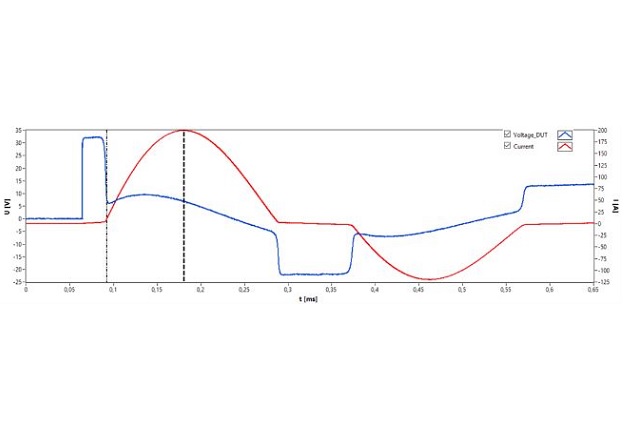
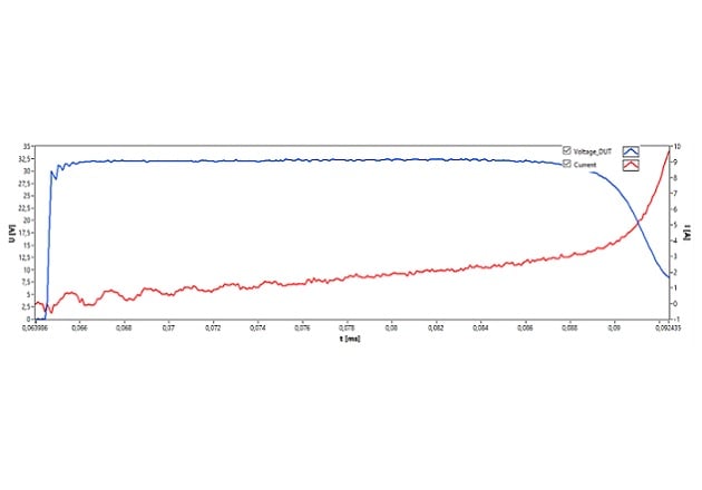
Figure 2: Demonstrated measurement results, from Bs&T pulse: (a) Total damped oscillation time decay (b) Expanding plot for the very-beginning damping period; Sample: 2 stacked tape wound core V144 and wound with labor strip of 0,5 m for 3 turns)
BsT&Technology and Data Evaluation
Damped oscillation method compliant modified IEEE 389 standard is a magnetic validation solution with transient high current amplitude, which enables large excitation. Its full reversal current enables further completion of the re-magnetization path and Bs&T pulse micro (<1kV) is a device of integration hardware/ software solution with the damped oscillation method. The fundamental operational principle of Bs&T Pulse micro has been presented in [2]. During the damped oscillation, the initial stored energy in the capacitor can be fully discharged to magnetize the common mode choke, and it provides large excitation due to fast switching speed of thyristor. An illustration of the initial measurement data of voltage and current time diagram is shown in Figure 2. In Bs&T pulse solution, all the waveform can be traced as raw data for analysis afterward.
(a)
(b)
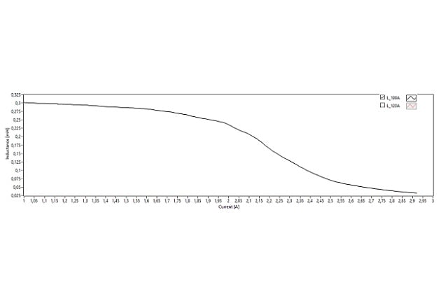
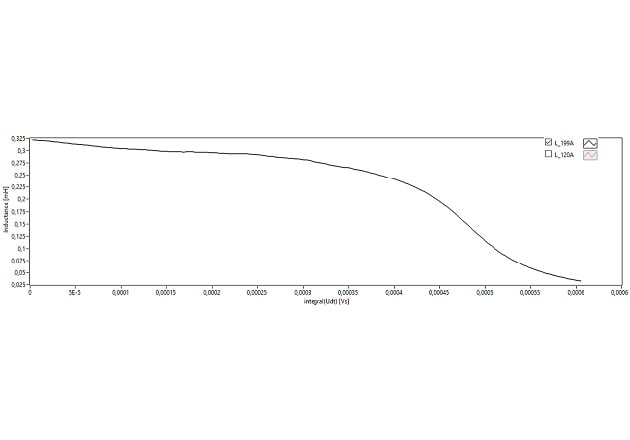
Figure 3: Measurement of differential inductance vs. magnetization current (a) and flux linkage (b) with damp-oscillation method
Description of common mode choke
The device under test is a common mode choke, which is cored with two tape wound cores, wound with laboratory cable (half meter, Rdc about 10 mΩ) with 3 turns, RAC about 34 mΩ and connected directly into terminals of BsT-pulse. BsT-pulse micro is equipped with a defined capacitor of 430µF inside, so that the nonlinear common mode choke and large storage capacitor form the LC resonance.
Inductance (magnetization)
The differential inductance can be directly read from the voltage and current curve by time around the first current peak amplitude, either vs. magnetization pulse current amplitude in (a), or flux linkage in (b)
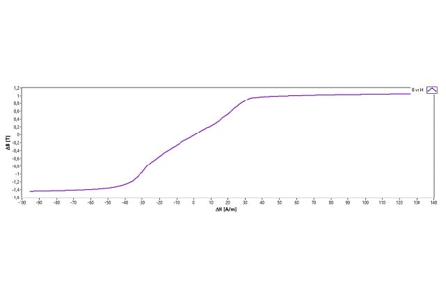
BH curve
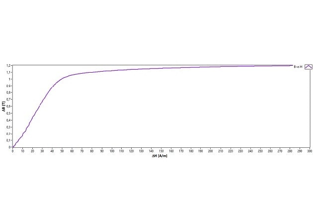
With given parameters, i.e. nominal value for magnetic effective length and cross section and number of turns, nonlinear BH curve can be validated, in Figure 4 (a) as unipolar and (b) bipolar excitation.
The differential inductance is roughly rated as 270 µH, properly given as the results seen in Figure 3, the nonlinearity towards current and flux linkage is given as well.
The bipolar excitation indicates the capability of noise absorption.
(a)
(b)
Figure 4: Magnetization curve of unipolar (a) and bipolar (b) excitation
Saturation and Leakage inductance
The saturation/leakage inductance is calculated as half sinusoidal curve Figure 5 [7]
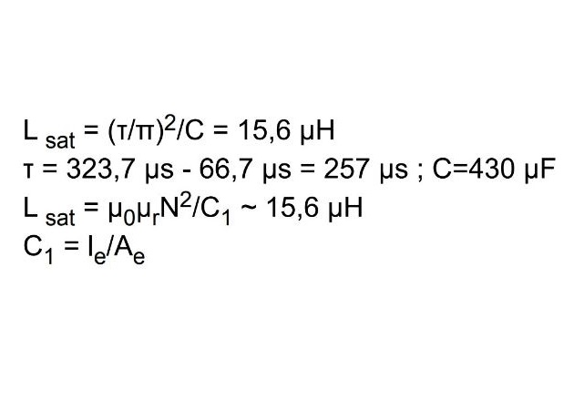
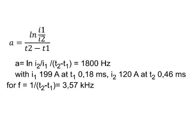
This value is confirmed by calculation with µr ~ 1 Damping coefficient is calculated as following [8]
Until now, the characteristic of this common mode choke cored with nanocrystalline material is completely accompanied:
Small signal as indicated with µ3 at 10kHz and 100 kHz, moreover
- Large signal delivers the choke performance
- Differential inductance vs. current and flux linkage Figure 3 (a) (b)
- Leakage inductance for the saturation phase, half sinusoidal time slot Figure 5
- Damp coefficient and corresponding resonance frequency
- Flux density after geometrical normalization indicated the typical Bs of nanocrystalline of 1,2 Tesla, seen in Figure 4
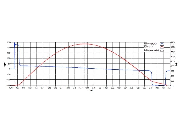
Figure 5: Estimation of leakage inductance for saturation interval, half sinusoidal time slot
resistance because only the voltage drop on the inductive part is to be taken into consideration to illustrate the magnetic properties. The precise measured value for AC resistance, as a by-product of impulse measurement, has significant importance for this particular application with respect of loss, mainly ohmic loss throughout saturation time period.
It is worth to mention that the nanocrystalline tape wound cores are mostly embedded in a plastic case, and it is difficult to stabilize the packing factor due to thickness of ribbon (~22µm) from manufacturing point of view.
It is difficult to have precise data, but with Bs&T-Pulse with given parameter by makers, it can be easily validated.
Theoretical model about impulse magnetization The very classical eddy current model assumes constant permeability over homogeneous magnetic cross section, which is not dependent of excitation. [4] In reality the two fundamental requirements for classical eddy current model are not given. Magnetization front model [5][6] distinguishes dynamic magnetization rate dB/dt and delivers reasonable result for dynamic differential permeability, which is proportional to specific resistance; in addition, available flux linkage in voltage second, which is reversal proportional to thickness of ribbon and magnetization rate dB/dt [T/µs], indicates different impulse energy will formulate different voltage and current decay and consequent BH curve, due to different dB/dt velocity of magnetization condition.
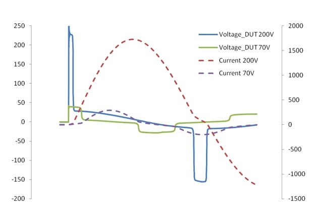
Figure 6: Damped oscillation voltage and current decay with same DUT but under different discharging voltage level i.e. dB/dt
Figure 6 demonstrates difference for two voltage and current decays with the same DUT (stress annealed nanocrystalline tape wound core, wound with half meter labor stripe ½ meter, with 8 turns. The same flux linkage consists of different height of voltage (50V vs. 220V) and pulse duration, and the current time curve is significantly different (200A vs. 1800A), the ratio is related to energy intensity in cap, because the leakage inductance at saturation is obviously equal for the same choke design.
The specific resistivity, ribbon thickness (rapid solidification process) and flux linkage (post annealing process) are material properties, which are depended on chemical composition and processing route by manufacturer. However, the magnetization rate is highly dependent on the applications. As common mode chokes withstanding impulse magnetization, the induced influence can be sensitized with different discharging voltage to illustrate different rates of dB/dt by the impulse results from Bs&T-pulse which provides the total core performance with respect of flux linkage capability to absorb the noise energy. The results using Bs&T-Pulse is the only proper validation methodology, which delivers core performance for common mode applications. The complete inductance analysis vs. demagnetization current and flux linkage are presented in Figure 3 (a) (b), and delta B vs. delta H Figure 4a, with given geometry for winding, and number of turns.
The differential inductance vs. current, from demagnetization path, is also important, because the first current peak eliminates the uncertainty of status of component under test, due to remanence, and this measurement ensures a direct comparison. The saturation inductance is of essential importance in terms of effective energy transfer in the saturated state and the peak current amplitude, the saturation inductance can be calculated as L sat = (τ/π)2/C where τ is the current pulse width, C is the value of the internal capacitor, the frequency of the current pulse during saturation can be determined from fsat= 1/2τ [7]
It is worthy while to mention, that core relaxation loss, pending on dB/ dt can be further studied with different discharge voltage, the nonlinearity of relaxation loss decoupled from excitation condition, i.e. frequency and flux density amplitude, is very much pending on specific time slot, where dB/dt ~ 0, while the current amplitude experiences its half sinusoidal peak.
Conclusion
Nanocrystalline tape wound cores with its high permeability, high Curie temperature and its diversification of manufacturing process capability (field and stress annealing) win increasingly preference of number of designers. However the conventional small-signal measurement cannot meet the requirement of specification with limit value alone. The difficulty of validation is discussed, and Bs&T pulse is offering a convincing validation solution for the components, both for core manufacturer and components manufacturer, and finally for end users. Further investigation can be performed with different magnetization velocity dB/dt, i.e. discharge voltage starting from some tens of voltage Bs&T-pulse micro until some tens of kV, with Bs&T-pulse macro.
Reference
[1] Magnetic Materials Hilzinger Chapter 17
[2] V144 https://vacuumschmelze.de/Assets/144-01-V%281%29.pdf
[3] Hanna Curve reloaded with Bs&T-pulse March Bodopower Yi Dou, JC Sun
[4] Über die Wirbelstromverzögerung magnetischer Schaltvorgänge W. Wolann and H.Kaden Zeitschrift f. techn. Physik 1932
[5] Dynamische Hystereschelifen von Rechteck-Ferriten Frequenz Bd. Stegmeier 17 1963
[6] The Growth of magnet. domains J. Bischop and P. Williams 1977
[7] Simulation of 3 staged MPC using customer characteristics of magnetic core J. Choi 2007
[8] Design of powder core inductor H.Skarrie 2001
About the Author
JC Sun is the founder of Bs&T Frankfurt am Main GmbH, a company located in the north of the metropolis Frankfurt am Main and specializes in the development and manufacture of integrated hyster loop measuring systems. He worked for two decades as a development engineer in power electronics; developing various soft magnetic materials and was a project manager for various companies.