Facebook
 Google
 GitHub
 Linkedin
Damp-Oscillation Solution for Validation of the Metal Alloyed Powder Core
The metal alloyed powder core is a kind of magnetic core, which is made from ferromagnetic alloy. After casting, it is pulverized, isolated with an insulation layer compacted with an inorganic binder under high pressure annealed in high temperature, and finally coated with epoxy coating to withstand high voltage stress.
The metal alloyed powder core is a kind of magnetic core, which is made from ferromagnetic alloy. After casting, it is pulverized, isolated with an insulation layer compacted with an inorganic binder under high pressure annealed in high temperature, and finally coated with epoxy coating to withstand high voltage stress.
Introduction
FeAlSi, NiFe, NiFeMo composition have dominated the second half of the last century. Since the beginning of the 21st-century diverse iron based alloy, cast and / or rapid solidified have been introduced to the market, where mostly iron-based alloy with nearly zero magnetostriction enables relatively stable magnetic performance undergoing the long process chain.
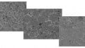
Normally the permeability of alloyed particles performs as high as to several hundred thousand while after the mechanical process, the powdered bulky bodies` permeability can be managed to several tens. These metal alloyed powder cores are mainly selected in power inductor applications, including inductance filters in grid-connection inverters, power factor correction (PFC) converters and output filters for middle-power switch-mode power supplies (SMPSs), where large flux linkage is required and at the same time certain inductance needs to be guaranteed. A microscopic photo of the powder core is shown in Figure1, where internal structure are shown and the structure gives the cores unique physical and magnetic characters.

Figure 1: Microscope photo of a metal alloyed powder core
One of the unique characteristics of the metal alloyed powder core is the gradual soft-saturation behavior: the permeability of the core material is highly dependent on the magnetic field strength on that thus no specific saturation condition can be defined, compared with ferrite materials or silicon steel sheets. Other notable characteristics of magnetics` powder core materials are high resistivity due to inorganic isolation surrounding the particle, that intragranular isolation is supposed to decrease volume eddy-current loss, and improve aging effect during the operation as wire-wound components under harsh environment.
Even metal alloyed powder cores have been applied for decades, the standardization concerning material classification and measurement validation are still in begin i.e. IEC63299 and IEC63300. Actually, the indeterminacy of standardization and measurement validation do bring challenges both for core designers and the application engineers: on the one hand, the expanding of standards for ferrite material IEC 60367 to enclose the metal alloyed powder core materials are still under negotiation, thus for core designers no consistent definition can be followed; on the other hand, several key parameters for the materials like Bsat and loss are missing on the datasheets of the materials, where the designers need for the component's optimization [1].
In this article, the materials validation challenges for metal alloyed powder cores are introduced and the damping-oscillation solution are presented with detailed principle description and technical discussion. Case studies of the solution and results in discussion are also presented to demonstrate the proposed measurement solution.
Validation Challenges of Powder Magnetic Cores
Due to the unique internal structure of metal alloyed powder cores and the corresponding performance, both the qualified definition and the core validation measurement meet significant challenges.
From the applications` perspective, how to compare powdered cores of the different labels and how to estimate the fundamental inductance value are always the two primary concerns during the component design. Generally, the inductance can be calculated with the permeability of the core material given by makers combining with the magnetic effective parameter of the core geometry, given by makers, nevertheless, it is rather difficult to apply the conventional method on the metal alloyed powder core due to the unclear definition between the alloyed materials and the shaped cores. Typically, the initial permeability of the alloyed particle can be as high as some hundred thousand while the powdered bulky body is normally managed as several of tens. Thus, in the beginning, the effective permeability must be distinguished when the manufacture providing the reference.
The cores owns the unique structure with distributed air-gap, the structure should still be regarded as a closed magnetic circuit, thus the length of magnetic flux`s path can be define then the magnetic field strength should be selected as the argument when depicting the permeability`s non-linearity. Under this circumstance, the given effective permeability as a constant has already lose its function as validated reference. Besides of undefined effective permeability, the AL value is another parameter provided by makers to the application engineers as only key reference with limit specification during the design. And the AL value suggested that a normalized inductance value with single turn for a closed magnetic circuit, which may be misleading.
The uncertainty of the AL comes not only from the non-linear effective permeability but also from the error from undefined measurement standard. First of all, the measurement for metal alloyed powder cores is still under negotiation but normally following the standard of magnetic components with rated current less than 22 A as in standard IEC 62024 ed 2, where the small-signal LCR meter with DC bias source is recommended as the validation solution. In addition, the limitation from the validation solution, including the measurement range of the excitation source and the inconsistent small-signal condition etc. make it difficult to distinguish the cores/materials and to make a fair comparison [2].
On the other hand, the measurement validation as a standard itself is worth to be further discussed. The small-signal LCR meter measurement as in IEC62044-2 is regarded as a established method to evaluate the metal alloyed powder cores, with benefit of convincing data sampling method and controllable excitation. However, the conventional small signal measurement with LCR meter is normally subject to its lower excitation capability on some conditions. Generally speaking, the distinguish between small-signal excitation and largesignal excitation locates on whether the driving source break the coercivity [3]. However, in terms of typical metal alloyed powder cores, the coercively is usually between some hundreds to thousands A/m, almost semi hard magnetic materials, it means the Rayleigh area of metal alloyed powder core is significantly large compared to other soft magnetic materials like ferrite, which the small-signal LCR meter measurement is not able to reach. Thus, a large-signal excitation would be a must to provide enough magnetizing condition to fully depict metal alloyed powder cores` performance.
With the modification of applying a DC current bias of to exciting the materials, the performance with H-bias can also be depicted in this straightforward way. Nevertheless, some drawbacks still limit the further expanding the application on metal alloyed powder cores: first of all, the controlled current source which mainly providing the bias current for the cores is limited by its output precision, especially when no bias is implemented during the measurement; secondly, when a relatively large current bias needed for magnetizing the metal alloyed powder cores with intrinsic distributed air-gap, the current output capability and precision will also bring extra system error during the hardware implementation. And the disadvantage to validate ferrite cored component is well described in standard IEC62024-2, Thus, it is necessary to introduce another “large-signal” validation solution combining with the small-signal LCR meter measurement to provide convincing validation for metal alloyed powder cores.
Powder Core Validation Solution with Bs&T-Pulse
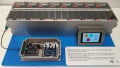
Damped oscillation method compliant modified IEEE 389 is a magnetic validation solution with transient high current amplitude, which enables large excitation and its full reversal current enables further completion of the re-magnetization path and Bs&T pulse micro is an integration hardware/ software solution with the damped oscillation method. The fundamental operational principle of Bs&T Pulse has been presented in [2]. During the damped oscillation, the initial stored energy in the capacitor can be fully discharged to magnetize the D.U.T. like a powder core to provide large excitation due to fast switching speed of thyristor, which is able guarantee adequate magnetization for the powder core materials. An illustration of the initial measurement data is shown in Figure 2 (a), which demonstrates the energy charging stage and the following damping oscillation process. In Figure 2 (b), the very-initial measured waveform is plotted, where the voltage waveform does not perform as a typical damping oscillation. In fact, in this period, the shape of the waveform is highly depended on the type of cores (such as hard or soft materials, open or close magnetic circuit etc.) as well as the performance of the energy-storage capacitor. In Bs&T pulse solution, all the waveform can be traced as raw data for analysis afterwards.


Figure 2: Demonstrated measurement results from Bs&T pulse:
a) Total measurement process (b) Expanding plot for the very-beginning damping period; (Sample: T106, 24 turns)

Figure 3: Measurement of differential and amplitude inductance with a damp-oscillation method
The differential inductance and amplitude inductance regarded as two fundamental parameters of a component can be directed measured by the method, as shown in Figure 3. The tested sample is a toroidal core with T106 shape and 24 turns of winding and the material composite is FeSiAl. In order to remove the error from residual magnetism, the second de-magnetizing process is selected to depict the performance. Generally from the aspect of application, the amplitude inductance always catch more attention because before saturation occurs for the cores, the amplitude inductance is normally regarded as a constant for induced operation analysis. However, as for components with metal alloyed powder, amplitude normally performs as a function if excitation current, which is usually called “soft-saturation” character.
This unique characteristic definitely cannot be observed only by small-signal measurement, due to the relatively small excitation range, neither by the modified small-signal method with DC bias because the un-continuous driving bias. As a comparison, the damping-oscillation method is a good alternative to directly find the amplitude and differential inductance owing to its oscillation process. As shown in Figure 3, the differential and amplitude inductance was measured with the current oscillating to be higher than 400 A and the “soft-saturation” character is depicted with its non-linearity inductance to adapt switch-inductor/ resonant applications.


Figure 4: B-H loop depiction and relative permeability as a function of excitation magnetic field strength (Core shape 2x E65 Xflux 040 with 139 turns)
Correspondingly, the performance of the powder core material can be evaluated. Particularly, here a testing sample is selected as demonstration: the core consists of two EE65 core in stacking from Fuss-emv and its DC and AC ESRs are measured as 294.5 and 320.0 mΩ [3]. In Figure 4 (a), a commutation curve depiction is shown by plotting the B-H data through the whole damp-oscillation period, then further investigation with anisotropy distribution to articulate the linearity of diverse magnetic material is possible.
As given in the core`s datasheet, only the AL value is given as a function of DC bias but no definition of measurement condition or the inductance evaluation is clarified, leading to much uncertainty of the parameters` precision. As the comparison, in the commutation curve, the B-H plot is able to give transparent measured performance evaluation for the core. For example, in the zoom-in plot the coercivity can be read for the core and the saturation flux density (Bsat) may be defined as when excitation H= 40000 A/m and also can be read directly from the first demagnetization path, (without disturbance of uncertain of remanence of DUT) . In addition, from the commutation curve, the saturation phenomenon, the coercivity and the relative permeability can work as curve-fitting reference in the future design guideline, such as building piece-wise core model and as training data group in the AI-based converters` optimization.


Figure 5: Combining validation for the inductors with metal alloyed powder cores
In Figures 4 (b) and 4(c), the relative permeability of the material can be calculated as the function of the excitation magnetic field strength or the magnetic flux density. Obviously, the soft-saturation phenomenon, whereas the relative permeability of the powder core material decreases with increase of the excitation, is precisely measured for the specific set-up condition, including the core shape, number of turns, temperature, particularly, a high excitation current can be provided by the Bs&T pulse solution was provided to guarantee a full-map depiction of the permeability shifting. Compared with the effective permeability from the datasheet, the measured relative permeability is able to provide much more information and as a reference for the component designers.
Combining Validation of Small Signal and Large Signal Measurement for the Powder Core
In this article, we demonstrate a combining validation for selected metal alloyed powder cores with large- and small-signal measurement to verify the full-map measurement concept. Firstly, Table 1 presents the parameters of the selected cores including the material composition, the initial permeability, the cores` shape and the weight of the cores. It is noticed that only two types of core shape, the T106 shape and the T184, are selected as the testing samples while different filling factors were implemented for the cores to construct the distributed air-gaps with different material performance. Correspondingly, the selected cores owns different weight/ density, which can be calculated the filling factor backwards.
An example measurement results for #6 sample with the combining validation are illustrated in Figure 5, along with a zoom-in figure to highlight the measurement by small-signal method. The measurement range of the small-signal and large-signal method are marked in different color in the figure and obviously the large-signal measurement has larger range however, the large signal cannot replace the smallsignal testing but only serve as supplementary methods. Besides, it can be found that the small-signal measurement can only provide dis-continuous measurement with discrete results while the damp oscillation method is able to conduct a continuous measurement in terms of the excitation.


Figure 6: Performance comparison between cores with single variables for cores
In particular, several comparison analysis are conducted on the measurement from Bs&T pulse solution: firstly, as shown in Figure 6 (a), a pair of cores (#5 and #6) with same raw material/ shape but different effective permeability are evaluated with B-H loop, which indicates the material filling-factor does influence the performance of the core; In Figure 6 (b), the comparison between cores (#6 and #7) with same shape/ permeability but built with different materials is made: when the magnetic field strength is increase from zero, the two core perform similarly based on the observation while, the permeability of the core with FeAlSi material start to decrease earlier than that with FeSi material. In this case, the performance comparison is clearly presented and the performance can be qualified as well. For the evaluation, the demagnetization process is selected to remove the error from the remanence.

Figure 7: Performance comparison between cores with single variables for cores in Table 1
In addition, the saturation performance are depicted for the samples, as shown in Figure 7: Theoretically, at 40,000 A/m of the magnetic field strength, the material should perform with 1.05 T for the magnetic flux density. In the measured data, all the measurement of the magnetic flux density are tested as 1.05 T, which can verify the theoretical results. Besides, the shape of B-H curve shows different among cores, which means an independent measurement is a must to depict the performance among cores, rather than mathematical calculation from a constant permeability; Particularly, the #7 sample with FeSi material and 90 of the permeability theoretically should meet 1.7 T at 40,000 A/m for the magnetic field strength, which can also be verified by the measured result.
Finally, the calculated Q-factor of the selected cores are plotted in Figure 8. The power loss measurement is always regarded as a challenge due to the intrinsic error from two separate measurement channel, especially on higher operation frequency. Though one solution with impedance compensation method was proposed to reduce the phase-angle error especially for high-frequency applications, the system error coming from propagation delay of sampling channels is always difficult to be totally corrected by during the hardware implement [4].
Thus, the data sampling method within single channel shows more potential than the conventional solution. In the Bs&T pulse solution, the issue is minimized by measure the voltage and the current within the same sampling channel and the power loss can be identified by Q-factor.

Figure 8: Q-factor measurement results from Bs&T pulse solution
It must be clarified that the Q-factor measurement by the damp-oscillating method. Refer to the system structure, the LC resonant circuit actually consists of the capacitor, which works as the energy source for oscillation, and the D.U.T, whose series resistance is the measured target. With a fixed capacitance value, the resistance can be calculated by using the current divided by the voltage when equals zero. Actually, this calculated value depends on the resonance frequency and also includes the equivalent-series-resistance (ESR) of the capacitance. Especially under hundreds of frequency conditions, this uncertainty is very hard to be deduced but anyway, a relative comparison can be made among tested components as long as keeping the same testing parameters.
Conclusion
The increasing use of powder brings both benefits and challenges for the application and the core validation. However, the conventional small-signal measurement cannot meet the requirement for the powder core manufacturers and application engineers. Bs&T pulse is offering a convincing validation solution for the components with powder cores and combining with the small-signal measurement, a full-map performance of the cores even the components can be unearthed maximally.
About the Authors
JC Sun is the founder of Bs&T Frankfurt am Main GmbH, a company located in the north of the metropolis Frankfurt am Main and specializes in the development and manufacture of integrated hyster loop measuring systems. He worked for two decades as a development engineer in power electronics; developing various soft magnetic materials and was a project manager for various companies.
Yi Dou is a Ph.D. student working on Power Electronics and has a strong background in high-frequency DC-DC converters, resonant converters, and magnetic design. He is currently under his Doctorate Degree in Power Electronics at DTU - Technical University of Denmark. He also holds a Master's Degree in Electrical and Electronics Engineering at DTU and also holds a Bachelor's Degree in Electrical and Electronics Engineering t Xi'an Jiaotong University.
Reference
- IEC 62044-1:2002: Cores made of soft magnetic materials - Measuring methods.
- “Hanna Curve Reloaded” by JC Sun, Bs&T Frankfurt am Main GmbH & Yi Dou, DTU Kopenhagen July edition of Bodo's Power Systems.
- https://www.mag-inc.com/Media/Magnetics/ Datasheets/00X6527E040.pdf
- Stolzke, Tobias, et al. “Comprehensive Accuracy Examination of Electrical Power Loss Measurements of Inductive Components for Frequencies up to 1 MHz.” Journal of Magnetism and Magnetic Materials, vol. 497, Elsevier B.V., 2020, p. 166022.
This article originally appeared in the Bodo’s Power Systems magazine.