Facebook
 Google
 GitHub
 Linkedin
An Intelligent Power Module for High Switching Speeds
This article discusses the differences between SLIMDIP-L and SLIMDIP-W and investigates what suits the market demand for compact and price-sensitive inverters
Intelligent Power Module solutions are the preferred driver solution in home appliances, especially washing machines, resulting from several advantages. Low power drives should fulfill not only high efficiency, noise, and reliability requirements but also the requirement of the optimized system cost. Mitsubishi Electric pioneered the DIPIPM™ concept in 1997, offering the solution to these market requirements since this time and continuing to present innovations in this segment.
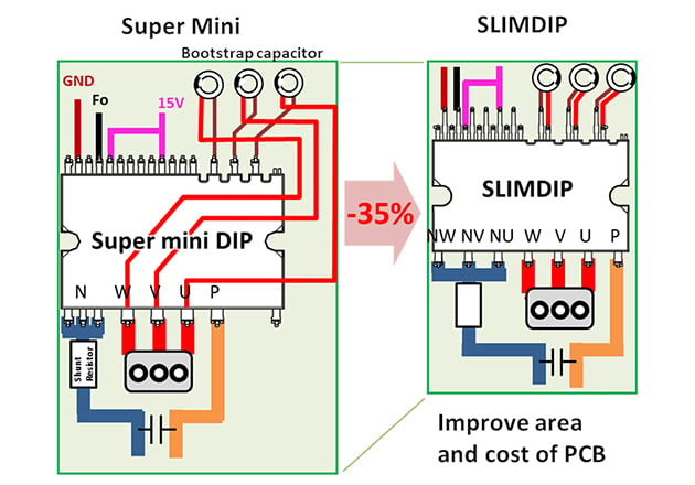
Figure 1: Reduced space requirements
The SLIMDIP™ family is the newest through-hole IPM, which offers reduced space requirements and an optimized pin layout compared to other DIPIPM™ products. The currently available products cover a motor power output range of 0.4kW (SLIMDIP-S) and 1.5kW (SLIMDIP-L).
Topology and Protection Functions
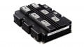
The SLIMDIP™ modules consist of six reverse conducting IGBTs (RC-IGBT), a high side driver IC, a low side driver IC and three bootstrap diodes with current limiting resistors. Direct control with a standard MCU is possible, due to the bootstrap diodes and the level shifter integrated into the HVIC, resulting in no need for galvanic isolation and an isolated power supply to control the high side switches. All dies are directly mounted on the lead frame without using a PCB inside the module, offering a market-leading lifetime performance. Figure 2 shows the used topology.

Figure 2: Topology integrated in the SLIMDIP module
Sensor-less control of the spin drive in white goods is state-of-the-art. Therefore the SLIMDIP™ modules are built with open emitters on the low voltage side, to allow independent current measurements via shunt resistors. The output signals of the current measurement can be used for the internal short circuit protection, which prevents the module to operate outside of the SCSOA. Furthermore, the SLIMDIPW integrates over-temperature protection with an additional temperature output with a linear temperature-voltage dependency, resulting in an easy-to-implement condition monitoring.
All SLIMDIP™ modules leaving the production line are tested regarding their static electrical characteristics and undergo a functional test with an inductive load. The results are recorded in an individual end-of-line test report in the factory.
The newly developed SLIMDIP-W module is a high-speed switching optimized version of the SLIMDIP-L module to fulfill the market demand of low audible noise inverters, which requires high switching speeds above the audible range of a human. Especially for home appliance products located in the living space, a low noise level is mandatory. For white goods sold in the EU, the EU energy label gives, besides the energy efficiency, the information about the noise level, allowing the customer the easy choice for a silent model.
Trends of the connected smart home lead the designer to develop the next generation of inverters in a shorter time and more cost-effective. Especially in the home appliance segment, the SLIMDIP-W fulfills these requirements. One of the main reasons to achieve compactness and price efficiency is the use of RC-IGBTs. With a blocking voltage of 600V and 2kVrms rated isolated thermal interface, the SLIMDIP-W is perfectly suited for single-phase input inverters, not only found in white goods, but also in fans and pumps, both for household and industrial use.
Differences between SLIMDIP-L and SLIMDIP-W
Developing the SLIMDIP-W module for high-speed switching required adaption on the chip level using the well-proven RC-IGBT technology. Rated for the same current as the SLIMDIP-L, a suiting point for high switching speeds in the trade-off curve of VCEsat vs Eoff is chosen to achieve an optimal loss performance. Additionally, the gate driver was optimized, resulting in faster switching times.
SLIMDIP-L and SLIMDIP-W are fully pin compatible. This allows use of the SLIMDIP-W in existing PCBs for the SLIMDIP-L without any modifications. Thermal design considerations are simplified as well, as the SLIMDIP-W uses the same type of insulation sheet.
Figure 3 shows a significant increase in efficiency at a higher switching frequency with sinusoidal modulation. With the same application conditions, the SLIMDIP-W allows a 30% higher output current at a switching frequency of 15 kHz. For low switching frequencies, the SLIMDIP-L is the optimal product.

Figure 3: Maximum allowable output current (Vcc=300V, VD=VDB=15V, P.F=0.8, fo=60Hz, Tj=125°C Tc=100°C, 3 phase modulation)
The differences in the losses can be explained with Figure 4. At the shown exemplary conditions, the SLIMDIP-W has higher conduction losses but decreased switching losses than the SLIMDIP-L. In sum, the SLIMDIP-W outperforms the SLIMDIP-L at these working conditions.

Figure 4: Simulated power loss comparison (Vcc=300V, VD=VDB=15V, P.F=0.8, fo=60Hz, Tj=125oC, 3 phase modulation)
Background is the trade-off between conduction losses and switching losses, which can be optimized for a specified switching frequency. With the aim to provide a product for low audible noise inverters, higher switching frequencies are preferred. Figure 5 and Figure 6 show the static conduction characteristics and switching losses respectively for both devices, illustrating the increased conduction losses, but decreased switching losses in the case of SLIMDIP-W.

Figure 5: Conduction characteristic comparison

Figure 6: Switching loss comparison
Higher switching speeds comply with steeper switching waveform. Therefore, parasitic inductances and capacitances influence switching behavior more. On the strength of the well-designed package design of the SLIMDIP™ series, the switching curves do not show parasitic effects despite the more tough conditions (Figure 7).


Figure 7: Switching waveforms (phase U, N-side)
Usually, faster switching speeds of the IGBT modules will increase also electromagnetic noise emissions. In this case, by adjusting the characteristics of the IGBTs, the EMI could be even improved, as shown in Figure 8.

Figure 8: Radiated noise improvement
Conclusion and Outlook
The new SLIMDIP-W module is the answer to the market demand for compact and price-sensitive inverters in-home appliances, and small industrial applications with high switching speeds. Built with Mitsubishi Electric’s long experience in producing transfer mold IPMs, high reliability can be achieved. Due to the functional compatibility of the SLIMDIP-L module, existing inverters can be optimized for high-speed switching with minor effort. Moreover, the SLIMDIP-W shows improvements in the radiated electromagnetic noise to reduce challenges in the inverter design stage. The SLIMDIP-W will be in mass production in Q2/2020, samples are available at the German Branch of Mitsubishi Electric in Ratingen.
About the Authors
Philipp Jabs received his Master of Science - Electrical, Electronics and Communications Engineering at RWTH Aachen University. He now works as an Application Engineer Power Semiconductors at Mitsubishi Electric Europe BV — an electronics and electrical equipment manufacturing company headquartered in Tokyo, Japan. It is one of the core companies of Mitsubishi.
Akiko Goto works in the Power Device Works division at Mitsubishi Electric Corporation located in Fukuoka Japan.
This article originally appeared in the Bodo’s Power Systems magazine.