Facebook
 Google
 GitHub
 Linkedin
Well Equipped for 48 Volts
This article discusses the advantages of the 48-volt systems technology for vehicles that helps reduce fuel consumption and environmental impact.
Some attractive advantages are offered by 48-volt technology for vehicles: It helps to reduce overall fuel consumption, reduces the environmental impact and can even improve the engine performance. The central component for this is a powerful buck-boost converter. With its power inductors and aluminum electrolytic capacitors, TDK offers key passive components for this purpose.
The number of electrical loads in vehicles is continuously rising: complex drivetrain management, convenience features such as auxiliary electrical heating systems, and safety-related systems such as ABS, ESP and many others are emerging as really high consumers of energy. The levels of power to be provided by alternators these days are rising in line with this demand. In the early 1980s, even luxury vehicles managed with alternator outputs of about 0.7 kW.
The power output required today, however, has already reached 3.5 kW – a seven-fold increase. The snag here is that if a 14-V alternator is generating this power, it means a current of 250 A is flowing. At this voltage-current ratio, however, a maximum efficiency of just 70 percent can be achieved. This necessitates a generator input power of 5 kW that must be supplied by the engine. A further drawback of the high total of currents is that large conductor cross-sections required, which add significantly to the weight of the vehicle and thus the overall costs.
Greater efficiency thanks to 48-volt systems
In view of the growing demands to reduce fuel consumption and CO2 emissions, a solution to this dilemma must urgently be found. This is where 48-volt technology offers attractive advantages, because it enables a number of fuel-saving features to be implemented that are not feasible with systems that only operate on 12 volts. These include:
- High-performance energy recuperation at >5 kW
- Extended start-stop functions, such as sailing or coasting
- Electrification of units such as turbocharger and electric power steering
- Support of micro-hybrid and mild hybrid solutions
The 48-volt systems are not a replacement for existing 12-volt architectures. Instead, this approach represents more of an extension to the 12-volt systems for handling powerful loads and is coupled to these systems by means of a buck-boost converter. Figure 1 illustrates the principle of this architecture. A conventional lead-acid or lead-gel battery is used for the 12-volt level, while a lithium-ion battery is used for the 48-volt level. Double-layer capacitors can also be connected in parallel here for improved storage of electrical energy during recuperation.
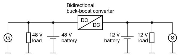
Figure 1: Principle of the combined 12/48-volt on-board power supply architecture. Most developments set the generator to the 48-volt level, enabling higher outputs and efficiency levels to be achieved. The two voltage levels are connected by means of a bidirectional buck-boost converter
Efficient coupling by means of buck-boost converter
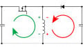
The most important component of a combined 12/48-volt system is the buck-boost converter which permits the bidirectional flow of energy between the two voltage levels and is designed for outputs of between 2 and 5 kW. Figure 2 shows the circuit diagram of such a converter. In the normal mode, the converter operates as a buck converter in order to output the power generated on the 48-volt level to the 12-volt system. In this operating mode T2 is continuously blocked and T1 operates as a switching regulator. The boost mode is necessary if an output is required at the 48-volt level. In this case, T1 is continuously connected and T2 operates in pulse mode. In order to keep ripple current and voltage to a minimum, systems with 6 or 8 phases, which can be serially connected, are used in practice.
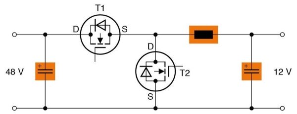
Figure 2: Circuit diagram of a buck-boost converter. Apart from the switching transistors, EPCOS power inductors and storage capacitors are the key components.
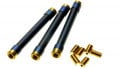
TDK has developed two new series of EPCOS power inductors for the storage and smoothing chokes in the converters. The ERU 27 series of inductors, for example, are SMD components. They are characterized by their high current capabilities and very compact footprint of just 30 mm x 27.8 mm (Figure 3, left). Their insertion height is 15.5 mm or 20.3 mm, depending on their inductance value. This compact design is made possible by the use of a flat winding that offers a high volume fill factor. The inductors are available in six versions covering an inductance range of 3.5 µH to 15 µH. Their saturation current varies between 19 A and 49 A. In order to increase the mechanical stability of the components on the PCB, the power chokes feature a third soldering pad in addition to the two solder pads for the winding.
As an alternative to the SMD types, the EPCOS ERU 33 types with their PTH terminations can also be used (Figure 3, right). This series offers a rated inductance of 3.2 µH to 10 µH and – depending on type – they are even designed for a saturation current of 79 A at an ohmic resistance of 0.85 mΩ. The dimensions of these power chokes are 33 mm x 33 mm x 15 mm. All the above types are suitable for operating temperatures ranging from -40°C to +150°C. They are also RoHS-compatible and qualified to AEC-Q200. In addition to the standard ERU 27 and ERU 33 types, customer-specific types with other inductance values can also be offered.
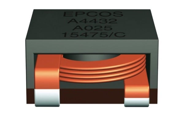
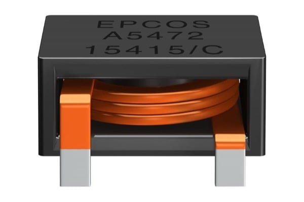
Figure 3: The compact EPCOS power inductors for buck-boost converters are available with current capabilities of up to 75 A.
Extremely vibration-resistant capacitors with high ripple current capability
Apart from the inductors, the key components in buck-boost converters are robust aluminum electrolytic capacitors for storage and smoothing. The EPCOS B41689 and B41789 series (Figure 4) are specially designed for the stringent demands of automotive electronics. They are characterized by their extremely high vibration strength of up to 60 g. The soldering star design and the version with cathode plate contacts on both ends of the capacitor enable optimized mounting with low ESL values.
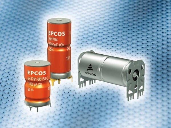
Figure 4: EPCOS aluminum electrolytic capacitors for automotive electronics are characterized by their extremely high vibration strength of up to 60 g and maximum operating temperatures of up to 150°C.
Thanks to their multiple internal contacts, these capacitors also feature low ESR values, which results in a higher ripple current capability and lower losses. Depending on type, the continuous ripple current capability of these capacitors at a case temperature of 125 °C reaches values of up to 29.5 A. The automotive series are designed for rated voltages of 25 V, 40 V (for 12 V) and 63 V (for 48 V). With these voltages they can be used in the new on-board power systems at both voltage levels. The capacitance range extends from 360 µF to 4500 µF.
In addition to the power inductors and aluminum electrolytic capacitors as key components, a series of additional TDK components is necessary for the implementation of buck-boost converters. These include MLCCs, current sense transformers and varistors.
Greater engine efficiency thanks to electric turbochargers
Apart from the electrification of conventional units such as pumps, 48-volt technology also makes it possible to run the engine more efficiently by using an e-turbocharger. Conventional turbochargers are driven by exhaust gases and their performance is very closely related to engine speed. In addition, they operate with a slight delay – also known as .
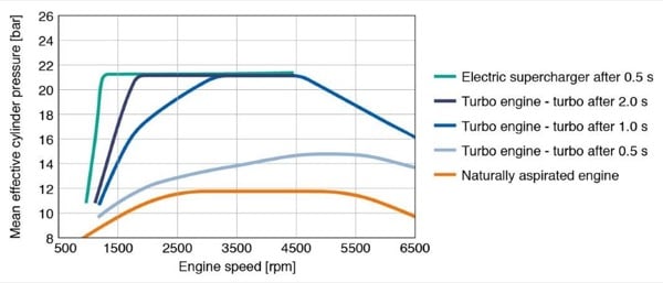
Figure 5: Engine with different chargers
This shortcoming is eliminated by electrically operated chargers, as they respond instantly and also at lower engine speeds, e.g. in urban traffic conditions, thereby offering better engine efficiency (see Figure 5). One more advantage: the e-turbocharger can be combined with a conventional turbocharger, either to further increase charging pressure, or so that the electrical charger can be switched off at high engine speeds.
This article originally appeared in the Bodo’s Power Systems magazine
About the Author
Christophe Jehle is the head of Products & Technologies at TDK Electronics, an electronics company based in München, Bayer, Germany that develops, manufactures and markets electronic components and systems, focusing on fast-growing leading-edge technology markets, which include automotive electronics, industrial electronics and consumer electronics as well as information and communications technology.