Facebook
 Google
 GitHub
 Linkedin
Benefitting from the Evolution of Power Transistors
This article discusses the evolution of power transistors and how they are redesigned and revised for increasing demands.
Evolution is an important part of any company enabled by technology. As a company with over 85 years of experience in drive technology, 77 drive technology centers in 50 countries around the world, and sales of over €3 billion in 2017/18, SEW-Eurodrive is recognized for its expertise in supplying key industries including automotive, airport baggage handling, transport and logistics, and beverages and liquids. As such, it understands how adopting the latest technological innovations is fundamental to remaining a leader in its field. As demand for higher efficiency has increased, SEW-Eurodrive also recognizes how the evolution of power transistors has helped it continue to deliver customer benefits.
The design of an auxiliary power supply provides the perfect example of how innovation and evolution work together. The PSU is designed to deliver between 300V and 1200V; delivering a voltage range as wide as this can be achieved using a Flyback topology using a high voltage power transistor capable of handling up to 1700V. The initial design was conceived around 2010 and at that time the choices were limited; the most viable option was a power MOSFET.
The Miller Effect
After designing the PSU it was clear that the main losses were as a result of the Miller Effect associated with the power MOSFET; the output capacitance of the device was causing losses that could be attributed to around a third of the total losses seen. These losses limited the operating frequency of the flyback circuit to 80kHz, further contributing to the losses. However, with no other options available at the time, these losses had to be endured.
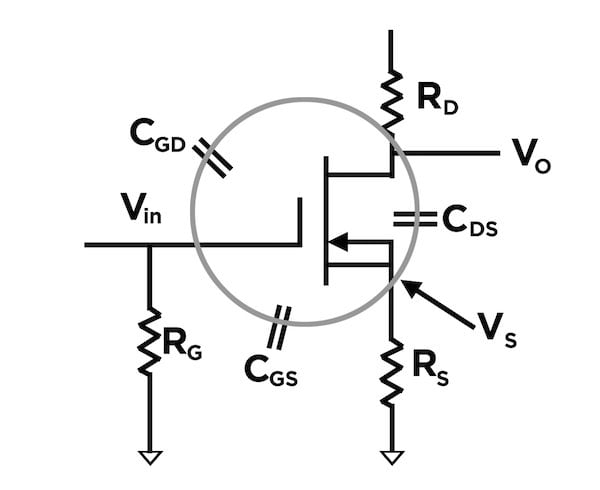
Figure 1. Example of the Miller Effect on a MOSFET
The Silicon Carbide MOSFET Solution
The advent of Silicon Carbide (SiC) MOSFET transistor technology allowed the design to be revised. This had many benefits, primarily the operating frequency could be increased from 80kHz to 135kHz and, with that, the number of ferrite core components required could be reduced by half, providing both a cost and space saving. This provided some benefits, but the starting resistance of the MOSFET meant losses were still experienced. Also, the gate voltage for SiC MOSFETs can vary, with gate-source voltages ranging from 25V/-10V to 19V/-6V and 20V/-4V; standard switching power supply controllers are only able to supply 15V and so it was necessary to add a voltage level shifter to the drive circuit.
The more recent move to normally ON SiC JFET technology represents the latest evolutionary stage of the PSU (See Figure 2) and brings with it benefits in terms of a simplified design, faster start times, lower losses, lower BoM cost, and reduced volume. This is in addition to being able to act as a second source to any silicon or SiC MOSFET.
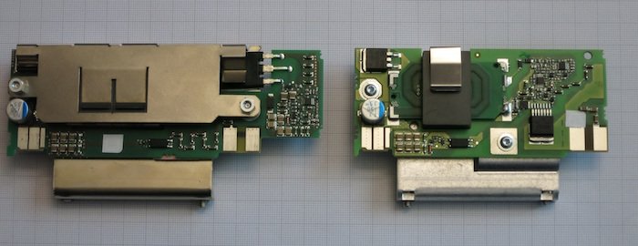
Figure 2. SEW-Eurodrive’s auxiliary power supply unit SiMosFet —> SiCJFet
SiC JFETs
The PSU design path from MOSFET to SiC MOSFET to SiC JFET over the course of seven years has delivered an overall reduction in losses of around 20%; moving from 90% efficiency to 92% efficiency. SEW-Eurodrive’s lead designer on the project, Klaus Marahrens, explained that a fundamental impact of moving to the JFET was removing the need for a start-up resistor. In a typical Flyback power supply that needs a start-up resistor, even a relatively high ohmic resistor will continue to dissipate power when the circuit is running. With a normally ON SiC JFET the start-up resistor isn’t needed, delivering an instant efficiency gain. A second benefit was that the level shifter required to drive the SiC MOSFET was no longer needed, and so it could be removed from the circuit completely, further lowering the BoM cost and overall size of the PSU.
The main functional block of the circuit (see Figure 3) uses a normally ON SiC JFET paired with a silicon MOSFET in a cascode configuration. Using a standard MOSFET means it can be driven from a low (0V to 10V) control signal, rather than a higher (around 18V) signal required by a SiC MOSFET. The cascode design also simplifies the start-up circuit; at start-up, the MOSFET drain voltage will reach steady-state at a level around the inverse of the JFET threshold voltage. This can power the circuit until the auxiliary winding is regulating. The application note uses a resistor and diode to join the MOSFET to the control circuitry.

Figure 3. A multi-output Flyback converter using the UJN171K0K
In the SEW-Eurodrive circuit, the MOSFET replaces the level shifter, as described earlier. The application note also describes a direct connection between the JFET’s gate and ground, however, in the case of SEW-Eurodrive, this is replaced with a resistor and diode combination.
The reason for this variation is to allow the switching characteristics of the JFET to be controlled directly, rather than using the MOSFET. This allows the switch-on and switch-off times of the JFET to be different, which in this case helped with EMC. For SEW-Eurodrive, the switch-on time could be very slow, by implementing a soft-switch design it was possible to avoid unnecessary EMC issues associated with fast switching signals. Conversely, in a Flyback converter the current is high during switch-off, for this reason it was advantageous to have a very fast switch-off time. Thanks to the capacitance in the winding, however, the voltage rise is slower, which results in lower switching losses in the JFET. In addition, the beneficial effects of having a gate voltage higher than 0V are an increased forward bias of the JFET and reduced on-resistance, further lowering losses.
The cascode circuit based on the normally ON SiC JFET supports higher switching frequencies; up to 400kHz potentially. For EMC purposes, however, the SEW-Eurodrive implementation operates at 135kHz. In fact, there were very few design changes needed to move from a SiC MOSFET to a SiC JFET, but the benefits are numerous, as described in this case study. This includes a faster start-up time; 20ms as opposed to 500ms for a design based on a SiC MOSFET.
As the primary power converters operate at higher power levels driving motor loads, using a SiC JFET is not currently viable. This is partly because the motor loads are not suited to the high dv/dt characteristics of the JFETs, which could potentially damage the motor windings, particularly if the type of motor connected is unknown. It should be noted that the turn-on and turn-off times, dv/dt, of the JFET can be controlled by varying its gate resistance, which in a cascode configuration is a function of the MOSFET. If the gate resistance is relatively high the dv/dt can be controlled by the rate of change of the MOSFET drain-source voltage, which effectively slows down the turn-on voltage of the JFET (for more details about how to control the dv/dt in a cascode configuration, refer to this article (PDF).
By moving to a cascode design based on a SiC JFET, SEW-Eurodrive has successfully reduced the losses in the auxiliary power supply converter by 20%. As a result, the heat generated by the design has also been reduced, allowing the overall power density to be increased and, therefore, the size of the PSU to be reduced.
In addition to lower losses and reduced size, the other main benefits of moving to the SiC JFET include reduced cost, thanks partly to the fact that the device is surface-mounted, meaning the entire design is now SMD, removing the need to use PTH devices completely. With a comparable BoM cost and lower assembly cost, the overall saving is as much as 20%.
About the Author
Christopher Rocneanu worked as the Business Development Manager at ROHM Semiconductor where he is responsible for the business development for products including SiC Diodes, MOSFETs, modules, gate drivers, and other integrated circuits as well as power resistors. He is skilled in Semiconductor Industry, wide bandgap, power electronics and marketing and he is a strong sales professional with a Master's degree focused in Industrial Electronics Technology from Christian-Albrechts-Universität zu Kiel.
This article originally appeared in the Bodo’s Power Systems magazine.