Facebook
 Google
 GitHub
 Linkedin
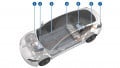
Allegro’s GMR Gear Tooth Speed Sensor Measures EV Transmission Rotations
Based on Giant Magnetoresistance (GMR), the new device is targeted at the ferromagnetic gears often employed by EV’s.
The ATS19480 speed sensor IC provides a single-channel solution that’s ideal for measuring the rotational speed on a moment-by-moment basis for hybrid and pure electric EV transmissions.
![]()
The ATS19480. Image courtesy of Allegro
The ATS19480 is a GMR IC designed for use in conjunction with ferromagnetic gear tooth devices in speed sensing applications. The device provides accurate rotational speed measurements over an operating air gap range that's 50% greater than its Hall-effect predecessor. Combined with advanced signal compensation, the ATS19480 provides increased system tolerances, increasing ease of design and reliability.
What are Magnetic Gears?
Like classical mechanical gears, magnetic gears also have teeth, only instead of physically interlocking teeth, they employ magnetic fields. In one type of implementation, the rotor is encircled by an evenly spaced number of permanent magnets around its circumference, just as a classical gear is encircled by its teeth.
The stator, composed of independently powered electromagnets in this system, encircles the rotor, and the changing, circulating magnetic fields interact with the rotor’s magnet, causing it to rotate in a motor-like fashion.
There is no mechanical connection between rotor and stator, so reliability and MBTF are drastically improved.
What is GMR
Unlike the Hall effect, GMR is based on electron spin, with a detailed explanation found in an Allegro White Paper written by Byron Cadugan. How this property is employed by the ATS19480 is illustrated in what Allegro describes as a magnetic profile, shown below. As illustrated, there are six vertical layers to the drawing.
![]()
Image courtesy of Allegro’s datasheet
The topmost portion is the gear as it rotates. Directly below that is the ATS19480. The gear is rotating such that a “tooth” passes the IC’s Pin 1 and then its Pin 3.
The next layer illustrates the sensing, low for the tooth, positive for the valley (lack of a tooth’s presence). The electrical consequence of the sensing is illustrated below that.
The second to last picture illustrates the ATS19480’s internal differential analog signals. Finally, the last illustration is of the IC’s output.
Compatibility with ASIL B
The automotive safety integrity level (ASIL) is a standard for functional safety for road vehicles. For this device, the ASIL level B assessment is now pending. To help achieve this criteria, the ATS19480 includes integrated diagnostics that are employed to detect an IC failure that would impact output accuracy.
The IC features built-in EEPROM scratch memory that offers traceability of the device throughout its operational lifetime. This ASIL reporting can be turned on or off as per the needs of the application.
Electrical Conditions
Maximum and minimum supply voltages are 24 and 4 volts, respectively, not including the voltage over RL, as illustrated in the typical application circuit shown below.
![]()
An application of the ATS19480. Image courtesy of Allegro datasheet
Supply current:
- Low current states, minimum and maximum, are 5.9 and 8 mA respectively.
- High current states, minimum and maximum, are 12 and 16 mA respectively.
Undervoltage lockout occurs at a maximum of 3.95 volts.
Physical
The ATS19480 operates over a temperature range of -40 to 150°C
Environmental
The unit is RoHS compliant