Facebook
 Google
 GitHub
 Linkedin
Implementing Effective Hot Swap Protection for AI Datacenters
This article discusses how to protect the hot swap stage in high-density AI datacenters by coordinating inrush current sensing, overvoltage clamping, and bulk capacitor discharge components.
AI workloads are driving rack power densities well beyond what traditional datacenter architectures were designed to support. Today’s bus voltages are migrating from 54 V and +/-400 VAC, and 800 VDC distribution is moving from concept to deployment to reduce energy losses, lessen required cabling, and help power the rapid growth of vast AI server clusters. These power transitions make the hot swap stage a key section that requires current protection, but it is also a known transient-susceptibility point in the rack power chain that needs to be mitigated.
The hot swap controller limits inrush current when a board is plugged into a live rail and acts as the circuit breaker for the load. However, the controller and the components it protects are themselves vulnerable to overvoltage events such as inductive kickback during faulty load disconnect and surge transients propagating from upstream. In dense AI racks running with tight voltage and current margins, overvoltage events can damage the controller, the load, or both.
Effectively protecting an AI data center’s hot swap stage depends on four key components that manage inrush current sensing, bulk capacitor discharge, and overvoltage clamping across both high-voltage rails and space-constrained, low-profile layouts. Certain types of products can manage inrush current sensing, bulk capacitor discharge, and overvoltage clamping for both high-voltage rails and compact, low-profile designs.

AI data center. Image used courtesy of Adobe Stock
Current and Voltage Envelope Protection
It is important to protect each function with components engineered for the current and voltage envelope of modern AI rack power.
Inrush Current Sensing
Hot-swap controllers regulate inrush current by sensing the voltage across an external current-sense resistor in series with the load. We recommend that designers source a current sense shunt that delivers high precision and power-handling capabilities.
The Bourns CSS2H-2512R-L500FE delivers 0.5 milliohm (mΩ) resistance with a 6 W power rating at 70°C and a low TCR. These resistor specifications can give designers the precision needed for accurate inrush regulation under the high transient currents typical of 48 V and High Voltage Direct Current (HVDC) racks.
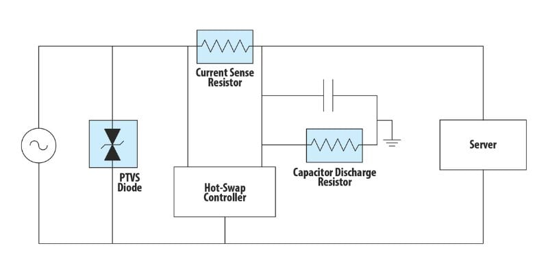
Figure 1. The protection topology around a typical hot swap controller.
Overvoltage Clamping—High-Voltage Fails
While the hot swap controller protects current transients, AI server rack architectures also need overvoltage protection with quick response times, which can require extreme energy dissipation.
For +/-400 VAC distribution and HVDC buses, a through-hole Power TVS (PTVS) diode is recommended. The Bourns Model PTVS3-430C-TH PTVS diode has a 430 V working voltage and absorbs peak pulse currents up to 3,000 A on an 8/20 µs surge waveform to meet the overvoltage protection requirements here. Where even higher rails are used, two Bourns Model PTVS3-430C-TH diodes can be placed in series to support working voltages up to 860 V.
Overvoltage Clamping—Low-Profile and Tight-Pitch Designs
Where board real estate is constrained, or working voltages are 86 V or below, a PTVS diode in a low-profile DFN package is suggested. These diodes support 1 kA and 2 kA peak pulse current capabilities, respectively. The 8 mm × 6 mm × 2.5 mm DFN package is ideally suited for tight-pitch designs. Similar to the through-hole PTVS diodes, DFN PTVS devices can be stacked in series for higher-voltage applications.
Bulk Capacitor Discharge
The hot swap controller limits the inrush current during events and charges a bulk capacitor at a controlled rate during board insertion to ensure safe system operation and prevent excessive inrush current that could damage components. A controlled charge and discharge profile is critical for safety, as it helps keep other components within safe operating area levels and prevents residual voltages from remaining after the hot swap event. A discharge path is required to clear residual voltage after the event, ensuring that energy stored in the capacitor does not pose a risk to downstream components or service personnel.
An example of a suitable solution is the Bourns Model UB3-8R75G2 wirewound resistor. With an 8-ohm resistance rating and a 2 W power rating, it can provide a controlled discharge path sized for typical hot swap hold-up capacitance, enabling predictable and repeatable energy dissipation.
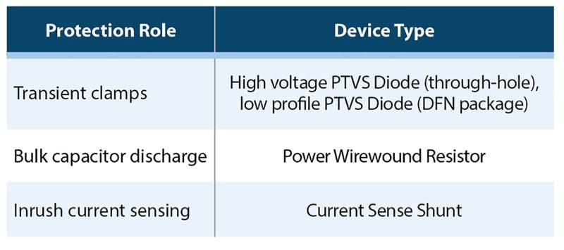
Fig. 2. Protection need and device types.
Achieving Full Hot Swap Current Protection
Using a single-source circuit protection component supplier eliminates the need to qualify multiple suppliers for the same protection function. Bourns’ broad portfolio gives designers the application-matched protection options, allowing them to select the right TVS clamp, current-sense resistor, and capacitor-discharge resistor for a given hot-swap circuit. A single source eliminates the need to qualify multiple suppliers for the protection function.
Also, it is important to specify circuit protection that has been engineered for AI rack voltage envelopes. Specifically, a PTVS model that features 430 V working voltage and 3,000 A peak pulse current addresses the +/-400 VAC. It can be stacked to address 800 VDC HVDC distribution architecture migrating into AI deployments. In addition, selecting a current sense resistor that can handle the high-current sense paths required is essential.
For series-stackable clamping, both through-hole and DFN-based PTVS devices support series configurations. Employing these components allows designers to reach 860 V and higher rails.
Precision is also needed for hot-swap control. Bourns resistors support ±75 PPM/°C TCR on a current-sense resistor and the 8 Ω / 2 W rating on the discharge resistor. With these capabilities, designers are provided with the traceable specifications necessary for closed-loop simulation and qualification.
Advantages of Coordinated Protection
Effective hot swap protection in AI datacenter power architectures requires a coordinated approach that addresses multiple electrical stress conditions. Inrush current sensing is needed to regulate the initial current flow during board insertion and prevent overstress of power components. Overvoltage clamping is equally critical to protect against transient spikes that can propagate through high-voltage distribution rails and exceed component ratings.
In addition, bulk capacitor discharge ensures that stored energy is safely removed after operation, reducing the risk of residual voltage impacting system reliability or service conditions. These protection functions highlight that no single solution is sufficient. Designing a combined approach is required to ensure safe, predictable, and highly reliable hot swap operation that effectively mitigates transient threats.
All images used courtesy of Bourns.