 Facebook
 Google
 GitHub
 Linkedin
Fixing Electrical Tape Slippage and Edge-Lift on Dry-Type Transformer Coils
Filament-reinforced tape can lift at the free end after heating while the band holds. Learn how identifying the stage at which lift first appears points to an application, heat, or impregnation cause.
Imagine a coil band that looks intact after application. At the inspection following heat treatment, its free end (where the tape terminates) is raised, while the rest of the band has not visibly moved. Should you change the end placement, adjust how the tape was applied, or try another tape?
The inspection tells you where to begin, but not when the end first lifted or why. This article addresses pressure-sensitive, filament-reinforced electrical tape used to hold winding materials, leads, or insulation on dry-type transformer coils. Such holding and banding uses appear in manufacturer literature; the actual surfaces and subsequent steps differ among designs.
Describe the Movement Before Choosing Another Tape
“The tape slipped” can describe three different observations:
- The band may move relative to the surface beneath it.
- A side edge may lose local contact while most of the band stays put.
- The free end may rise where it terminates.
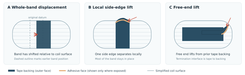
Three ways a coil band can fail: (A) the whole band shifts from its original position, (B) one side edge lifts locally, and (C) the free end lifts from the prior tape backing.
If insulation paper or a conductor also changes position, record that movement separately. A visible shift is not, by itself, proof of adhesive creep, separation at the interface, or failure within the adhesive.
Mark a representative assembly outside the bond area. Photograph the same location with a scale, orientation, and process stage. Record displacement and extent of lift; keep an untouched comparison if inspection may disturb the edge.
Breaking strength describes resistance to pulling the tape apart. Adhesion concerns its bond to a contact surface. Cohesion is the adhesive's internal strength. Tack defines how quickly it initially grips under light pressure. A higher value in one of these categories doesn't tell you whether the end is lifting from its own backing or the whole band is moving on insulation. Locate the change before ranking replacement tapes.
Find the First Stage at Which the Defect Is Visible
Inspect where the process permits: after application, holding or handling, demolding or pressing, drying or preheating, and impregnation and cure if those steps occur. Do not interrupt a controlled process to create an inspection point. If the first inspection is after cure, the defect could have arisen at any earlier stage.
Keep these records alongside each inspection:
- Record tape grade and lot, storage and use conditions, and the surface under the adhesive. If the defect follows a particular roll or surface, that variable should drive the next comparison.
- Record width, direction, overlap, end placement, tape application tension, and pressing method. A machine setting is not necessarily the tension at the tape. Note roll, substrate, or ambient temperatures and visible dampness when they vary.
- Note waiting, handling, the part's time–temperature history, treatment medium, and sequence. These records help select comparable pieces. This checklist reflects supplier application questions about substrate, exposure, and load.
Examine the Contact and the Path of the Band
Identify the Surface Under the Adhesive
Trace the band around the coil: enameled wire, copper strip, insulation paper, a resin-treated surface, or its own backing may lie beneath it. At each lifted region, note the surface, loose layers, contamination, wrinkles, or gaps. Photograph contact before disturbing the edge. Record how the band was pressed down (roller, tool or hand), the pressing path, and whether it reached the corners and free end.
A steel-panel adhesion value belongs to its test conditions. The February 2012 sheet for 3M Electrical Tape 1039 reports typical adhesion to steel separately from breaking strength; neither predicts the processed winding interface. A coupon with the actual surface can screen a difference, but cannot reproduce curvature or a loaded end. On representative pieces, compare permitted pressing methods while keeping tape, surface, path, and later steps identical; inspect the same locations afterward. Use insulation-approved cleaning procedures, if cleaning is compared. Do not assume more pressure helps.
Record Tape Application Tension, Then Compare It Deliberately
Keep tape application tension distinct from conductor-winding tension. Record equipment settings, measured tape tension if available, and start and stop behavior. For manual work, record the method. Backing elongation at break does not supply a banding-machine setting.
Tension and pressing are different operations, though both can affect contact with a contour. On approved test pieces, compare feasible tension settings while keeping the tape, surface, path, pressing method, and later process as consistent as possible. Check whether the affected location changes repeatedly. The adjusted band must still meet its holding requirement throughout the process.
Inspect Overlap and the Final Turn Separately
Lateral overlap between adjacent turns and the bonded length of the free end are different dimensions. Record both. Does the end finish on insulation, on metal, or on the tape's backing? Does it cross a step or corner? How much of the end actually contacts the surface? A change in lateral overlap need not repair a free end that is attached to a different interface.
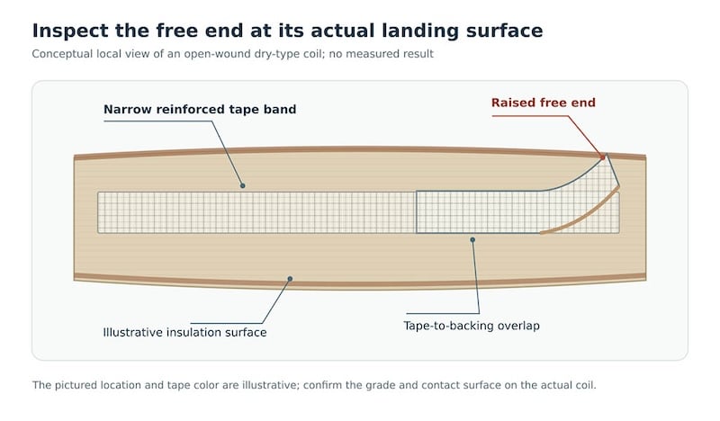
The free end of a narrow reinforced tape band lifts at its landing surface, near the tape-to-backing overlap on an open-wound dry-type coil.
The 1039 data sheet associates a back-side coating with controlled unwind and anchoring; its product page also describes coating-related bonding during transformer baking. Check the intended behavior of the specific tape-to-backing interface. Those descriptions neither diagnose this lift nor prescribe baking for other tapes. Compare approved end placements on representative pieces after the relevant steps.
Separate Heat Exposure From the Full Impregnation Route
Pressure-sensitive contact on application, any product-specific thermal setting of an adhesive, and curing of the transformer's varnish or resin are different events. The 2012 sheet calls 1039's adhesive thermosetting acrylic while also saying it requires no heat or other preparation before or after application. A broader 3M selection guide describes differences among tape constructions and adhesive systems. These documents are a reason to request the instructions for the actual grade, rather than deriving a pre-bake schedule from “acrylic” or “rubber.”
Record the part's time–temperature exposure as closely as the approved process allows; an oven setpoint alone may not describe the sample's experience. Identify the treatment medium and sequence. If vacuum, pressure, or transfer steps are used, record them along with any visible changes in contact, dimensions, bubbles, or flow marks. This helps choose which part of the full process needs comparison.
On pieces initially prepared alike, compare baseline, heat-only, and complete processing when authorized. Match heat histories where possible. Change after heat alone directs attention to exposure and contact under load; change only after full processing directs attention to its added medium and operations. Omitting impregnation also changes wetting and heat transfer, so the contrast cannot isolate chemistry. A nominal thermal class supplies neither an oven recipe nor hot holding data for this coil.
Build Comparisons That Can Change the Investigation
Choose the piece for the question. A coupon with the actual surface can screen contact differences. For tension, overlap, or end placement, use an approved assembly reproducing the relevant curvature, interface, and application method; document its differences from the product. Confirm a promising change on the relevant coil through its complete process under normal trial controls. This is an investigation design, not a standardized slip test.
Use the observed location and first visible stage to pick a comparison that separates plausible explanations. This table is a planning aid for an authorized trial.
Comparison plan linking each observed defect pattern to what to inspect, what to compare and what the result can justify.
| Observation | Conditions to inspect | Focused comparison | What the result can justify |
| Position changes immediately after application | Surface, pressing and tape tension | Same surface; vary one permitted application condition | Repeat a linked difference through later steps; otherwise examine surface and path |
| The free end lifts most | Landing surface, bonded length and contact | Same tape and process; compare approved end placements | Repeat a promising placement through the full process; otherwise inspect end contact and tape backing |
| A corner or side edge lifts | Local contact and shape | Same location; compare permitted pressing or path changes | If lift stays at the corner, inspect geometry; if it follows application, repeat that comparison |
| Change appears after heat | Part temperature history and load | Comparable baseline and heat-exposed pieces | If heat reproduces it, examine exposure and holding; otherwise compare later steps |
| Change appears only after impregnation/cure | Medium and added pressure, vacuum or transfer steps | Comparable heat-only and full-process pieces | Compare added steps in a narrower authorized trial |
Table note. Heat-only and full-route pieces differ in more than chemical exposure. Treat any improvement as a reason to repeat and extend the trial under the stated conditions.
Take the opening example: only the free end is raised at the post-heat inspection; the side edges remain seated. Compare approved end placements on pieces with the same grade, surface, pressing method, and heat sequence. That tests the free end without switching adhesives. If improvement repeats, verify holding and insulation requirements through later steps. If it doesn't, inspect end contact and pressing records, then compare the interface or exposure. Neither result alone identifies one cause.
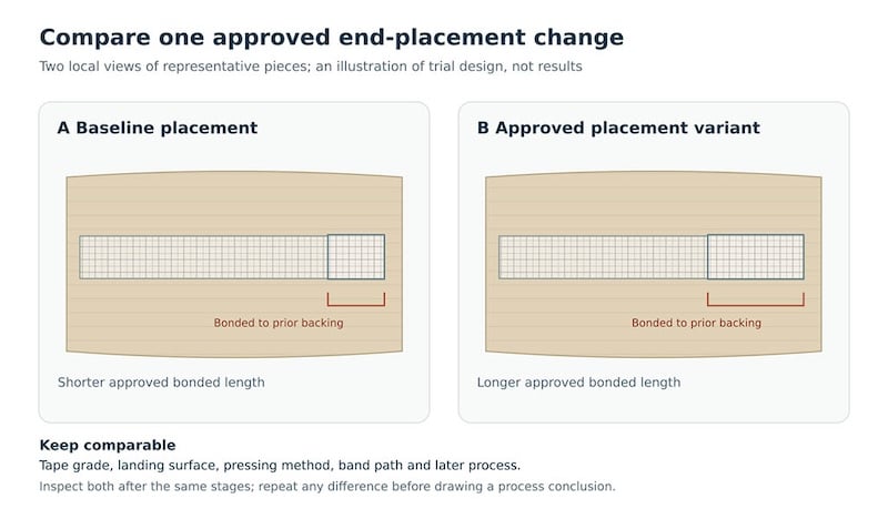
Baseline placement (A) has a shorter bonded length to the prior backing than the approved placement variant (B).
Keep the current method as baseline; use a documented good lot as another reference if comparable. Log conditions that cannot be matched. One-factor screening may need a further comparison because tension, surface, and exposure can interact.
Repeat baseline and comparison pieces to see ordinary variation. Fix inspection times and methods in advance; compare the size and repeatability of a change with assembly requirements. Record displacement, lift, and contact appearance consistently. If images cannot answer the holding question, use an engineering-approved test suited to the interface and load. One better-looking sample is insufficient for approval.
Decide When to Adjust the Process and When to Evaluate Tape Alternatives
When the same tape repeatedly improves under a feasible application change, determine whether operators or equipment can hold that setting or end placement in normal manufacturing. Run the candidate through the complete process it will actually encounter and check the original holding and insulation requirements.
Start material evaluation sooner if grade-specific evidence already shows that the required use or processing conditions are outside the present tape's scope. Otherwise, evaluate alternatives when the present grade still misses a predefined holding requirement under controlled, practical application conditions. Ask for missing documentation before concluding that a poorly described tape is unsuitable. A temperature label by itself, or the location of a broken backing or adhesive, does not settle the choice. Compare reinforcement and backing, adhesive system, the actual bonding interface, and evidence for the specified heat and treatment medium. An overview of Power Transformer Insulation can frame material categories; grade-specific documents and trials decide whether a candidate fits this coil.
When working with a supplier:
- Ask for the exact grade and data-sheet revision.
- Separate typical results from specifications; identify the substrate and method behind adhesion data.
- Request uses, limits, processing instructions and tests involving the named varnish or resin, with conditions and outcomes.
- Verify the scope of any claimed recognition.
UL discusses chemical compatibility when adding fastening tapes to evaluated insulation systems; that does not test holding on this coil.
Set allowable displacement, lift, and holding criteria from product and process requirements before final trials. Confirm performance through the complete manufacturing process and check the insulation system's other requirements under the applicable change procedure. Include material lots, equipment, or operators where their variation matters for approval. Send the supplier the surface, grade, defect images and inspection stage, thermal and chemical history, and comparison records. Once approved, record the grade, application conditions, end placement and inspection points in the manufacturing instructions.
Return to the opening example: a raised free end after heat treatment, with the side edges still seated. Finding the stage where the lift first appears, then comparing one approved end-placement change against the baseline, gives the next step a basis in evidence rather than a guess about the tape. Whether the answer is a process adjustment or a different tape, the records collected along the way support the decision.
All images used courtesy of Jiaxing Risure New Material