Facebook
 Google
 GitHub
 Linkedin
The Mechanics of Operating DC Generators
Learn about the operating mechanisms of DC generators involving components like the armature, commutator, brush assembly, and field windings. Various configurations, such as series-wound, shunt-wound, and compound-wound generators, cater to applications with varying voltage regulation characteristics.
The working mechanism of a DC generator involves the armature's rotation through the stationary magnetic field of field windings, inducing voltage. Different configurations offer distinct voltage regulation characteristics, including series-wound, shunt-wound (self-excited and separately excited), and compound-wound generators. Practical measures such as flashing the field for non-producing generators contribute to optimizing DC generator performance.

Image used courtesy of Adobe Stock
Parts of a DC Generator
The typical DC generator consists of four main parts: the armature, the commutator, the brush assembly, and the field windings. The armature typically has wire loops mounted on a rotating shaft. Some mechanical energy is used to rotate the shaft. The mechanical energy may be water, steam, or air, turning a turbine attached to the shaft. Other methods may also be used.
The ends of the armature loops are connected to the commutator. The commutator provides a surface on which the brush assembly makes electrical contact, allowing current to be drawn through the assembly from the revolving armature windings. The field windings, connected to a source of excitation current, do not revolve; instead, they remain stationary. Figure 1 shows the parts of a DC generator.

Figure 1. Parts of a DC generator. Image used courtesy of Amna Ahmad
As the excitation current flows through the field winding, it creates a magnetic field. As the armature is rotated by mechanical energy, the loops of wire in the armature rotate through the magnetic field of the field windings. This induces a current and voltage in the armature windings. The amount of generated voltage is determined by the strength of the magnetic field and the armature's rotation speed. A stronger magnetic field caused by increasing the excitation current will produce a higher output voltage. Likewise, rotating the armature faster cuts more lines of force of the magnetic field, resulting in a higher output voltage. Therefore, varying either the excitation current or the rotation speed will directly affect the generated voltage.
The load is connected to the armature windings through the brushes. Therefore, the current drawn by the load must pass through the brush assembly.
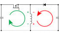
The purpose of the commutator is to maintain the polarity of the DC voltage generated by the armature. Notice in Figure 2 that the field is connected to a source of DC excitation current. Observe the polarity of the field windings. Also, notice that the connections to the field do not change. The field will always have the same magnetic polarity. Now watch what happens as the armature revolves. When mechanical energy is applied to the armature in Figure 2, the magnetic field of the field windings causes a current to be induced into the armature winding. Now look at Figure 3, Figure 4, and Figure 5. The commutator maintains the polarity of the DC voltage produced within the armature, causing the load to continue to receive the same polarity of voltage.

Figure 2. A magnetic field is created by applying a DC excitation current. Image used courtesy of Amna Ahmad

Figure 3. Mechanical energy causes the shaft to rotate. The magnets represent the magnetic field. Image used courtesy of Amna Ahmad

Figure 4. The shaft has rotated 90°. The polarity of the brushes remains constant. Image used courtesy of Amna Ahmad

Figure 5. The shaft has rotated 180°. The brush polarity remains unchanged. Image used courtesy of Amna Ahmad
Sometimes, excessive arcing will be noticed when the brushes contact the commutator. This may result from the brush assembly being out of proper position. The brushes must be set to a position known as the neutral plane. To set the brushes to the neutral plane, refer to Figure 6 and follow these steps:
1. Connect an AC voltmeter across the shunt field winding.
2. Obtain a low-voltage AC source.
3. Connect the AC source across the armature.
4. Carefully move the brush assembly back and forth, noting the change in voltage as indicated on the AC voltmeter.
5. Place the brush assembly in the location that produces the lowest indicated voltage on the AC voltmeter.

Figure 6. Set up to find the brush's neutral position. Image used courtesy of Amna Ahmad
Connecting DC Generators
DC generators can be connected in one of four ways: series wound, self-excited shunt wound, separately excited shunt wound, and compound wound.
Series-Wound DC Generator
Figure 7 shows a series-wound DC generator because the field is connected in series with the armature. In a series-wound generator, the series field excitation current is the same one supplied to the load. A high-resistance load draws minimal current from the generator, causing minimal voltage. Should the load become less resistive, the current will increase, causing an increase in generated voltage. The net result is that the generated output voltage of a series-wound generator varies with the load. Therefore, the series-wound generator has poor voltage regulation. Series-wound generators are rarely used today.

Figure 7. Series-wound DC generator. Image used courtesy of Amna Ahmad
Self-Excited Shunt-Wound DC Generator
A second way to connect a DC generator is to connect the field windings across or parallel to the armature. This configuration, known as a shunt-wound DC generator, is shown in Figure 8. A shunt-wound DC generator can be self-excited or separately excited. Figure 8 shows a self-excited shunt-wound DC generator. In this circuit, the shunt winding receives its excitation current from the residual magnetism within the stator poles of the DC generator. Usually, enough magnetism remains to induce a small excitation current in the field windings. The excitation current is sufficient to cause the generator to produce power when the armature is rotated. As the armature rotates, more voltage is created, which induces more current, thus making more voltage, and so on. Because the excitation current of a self-excited shunt-wound generator is not the same as that of the load current, its voltage regulation is better than a series-wound generator.

Figure 8. Self-excited shunt-wound DC generator. Image used courtesy of Amna Ahmad
Sometimes, a self-excited shunt-wound generator fails to produce a voltage. This is usually because the residual magnetism within the pole pieces has been lost. The problem can be easily fixed through a procedure called flashing the field. Figure 9 shows the connections to flash the field and restore the residual magnetism. To restore residual magnetism:
1. Disconnect the field from the armature and note the polarity of the field.
2. Get a low-voltage DC source; a 12-volt automotive-type battery suffices for a 120-volt- to 600-volt DC generator.
3. Establish the connection of the DC source across the field winding, ensuring it aligns with the polarity identified in Step 1.
4. Keep the DC source connected for around 10 minutes.
5. Disconnect the DC source.
6. Reconnect the field to the armature. Be sure to observe polarity.
The generator should now function normally.

Figure 9. Flashing the field of a shunt-wound DC generator. Image used courtesy of Amna Ahmad
Separately Excited Shunt-Wound DC Generator
Figure 10 shows the connections for a separately excited shunt-wound DC generator. Notice that the shunt winding now receives power from a separate DC source. Most DC generators are connected in this manner. The separately excited shunt-wound generator offers better voltage regulation than the self-excited generator. However, the separately excited shunt-wound generator is more costly because of the additional source of DC required to provide the field excitation current. Having a separate excitation current source allows the excitation current to vary with the load. This means that as the load increases, more excitation current can be provided, which causes the generated voltage to remain constant and not decrease. Likewise, as the load becomes lighter, less excitation current can be provided, which again results in the generated voltage remaining constant instead of increasing.

Figure 10. A shunt-wound DC generator with separate variable excitation current. Image used courtesy of Amna Ahmad
Compound-Wound DC Generator
The compound-wound DC generator is shown in Figure 11. A series field is connected in series with the armature. A shunt field is connected parallel to the armature. This arrangement is the reason why the generator is called a compound-wound generator.

Figure 11. Compound-wound DC generator. Image used courtesy of Amna Ahmad
The series and shunt fields can be connected in two ways. If the fields are connected so that their magnetic fields aid each other, the compound-wound generator is said to be a cumulative wound. Figure 12 shows a cumulative-wound compound-wound generator. This generator has excellent voltage regulation.

Figure 12. Cumulative-wound compound-wound DC generator. Image used courtesy of Amna Ahmad
If the fields are connected so that their magnetic fields oppose each other, the compound-wound generator is said to be a differential wound. Figure 13 shows a differential-wound compound-wound generator. This generator has poorer voltage regulation, but its output current is practically constant. Differential-wound compound-wound generators are commonly used to power arc lights and welding applications.

Figure 13. Differential-wound compound-wound DC generator. Image used courtesy of Amna Ahmad
DC Generator Takeaways
DC generators play a pivotal role in electrical systems. Understanding the fundamental components, working mechanisms, and configurations allows engineers to design, troubleshoot, and optimize DC generators. This knowledge is essential for ensuring efficient energy conversion and practical utilization of DC generators in various power systems applications.