Facebook
 Google
 GitHub
 Linkedin
Smarter Packaging for Demanding Power Applications
The new baseplate-less flow S3 package extends the power range of Vincotech’s well-established flow housing family. The housing is tailored for applications demanding more power in a small footprint for example solar inverters or motor drives.
The new baseplate-less flow S3 package extends the power range of Vincotech’s well-established flow housing family. The housing is tailored for applications demanding more power in a small footprint for example solar inverters or motor drives.
Introduction
Engineers aim for higher power ratings, increased power density, and, ultimately, more power in the same frame size. An increase of ceramic substrate size to accommodate the required semiconductors for higher power rating, while keeping a small package footprint, is the key. The sweet spot comes by lack of a copper baseplate and by lack of system solder, which results reduced cost and increased reliability. A new baseplate-less package with a single big ceramic substrate will be introduced in this article.
Flow S3 Package Description
The new baseplate-less housing flow S3 comprises 67% more ceramic area than flow 1. The outline dimensions of flow 1 are increased along with the two blue arrows in the y-direction (Figure 1) while keeping the screw hole distance and the dimensions in the x-direction. Besides the dimensional increase, the thermal performance was in special focus during flow S3 design. The ceramic substrate thickness is reduced and the contact pressure between ceramic and heat sink is increased. The flow S3 housing lacks a heavy copper baseplate which makes it a very affordable module.
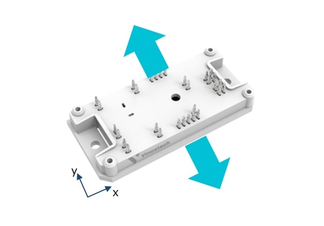
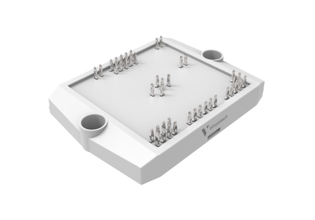
Figure 1: flow 1 (left) and novel flow S3 (right)
With the benefit of their low stray inductance, the 12 mm housing prominently features applications where fast switching speed and high efficiency are needed. Low inductivity is also supported by the free placement of pins and the possibility to integrate ceramic capacitors, resulting in low voltage overshoot. Plastic housing material with a comparative tracking index of 600 (CTI600) makes the flow S3 housing the best choice for 1500 V applications.
Pressure Distribution and Thermal Resistance
High thermal performance is equivalent to a low thermal resistance Rth(j-s) from the semiconductor junction to the heat sink, which is the key for higher power density. An improvement in the thermal resistance can be obtained by optimizing the two main contributors on the thermal resistance: ceramic substrate and thermal interface material (TIM). Especially for the latter the pressure or contact force on the interface is influencing the thermal resistance.
Figure 2 shows the pressure distribution between DCB and heat sink of flow S3 and a competitor package. The novel baseplate-less package flow S3 appears with overall higher contact pressure and more uniform pressure distribution.
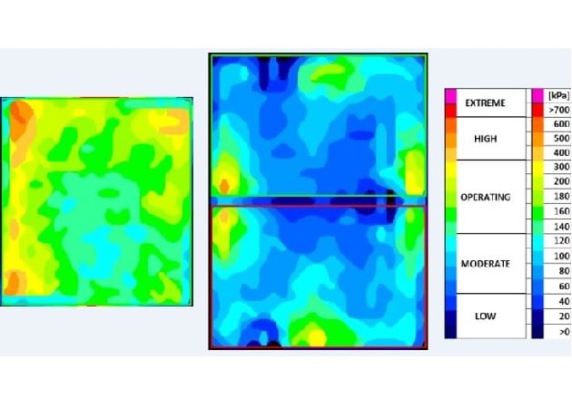
Figure 2: Pressure distribution of flow S3 (left) and a competitor package (right)
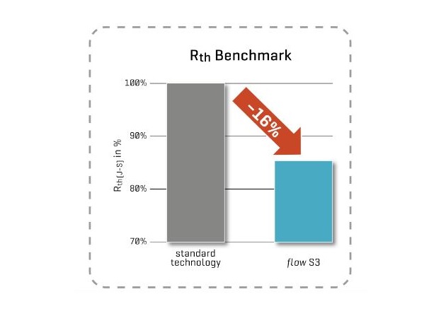
Figure 3: Rth benchmark of flow S3 and standard power module technology
The pressure distribution is only the first indicator for better thermal performance. The proof is furnished by the measurement of the thermal resistance Rth(j-s) between the semiconductor junction and the heat sink (Figure 3). The thermal resistance of flow S3 is 16% lower than Vincotech standard technology.
The consequence of smaller thermal resistance is a lower chip junction temperature at the same output power and, thus, longer lifetime. At the same junction temperature, the housing with the lower thermal resistance can deliver higher output power.
Validation of no TIM Pump-out
The pump-out of the thermal interface material (TIM) is well known from baseplate modules. The root cause of TIM pump-out is the thermomechanical movement of the baseplate at changing temperatures. The temperature change can be active by increase or decrease of the power or passive by a change of ambient temperature. In both cases, the thermo-mechanical movement of the baseplate pushes the TIM material to the edges of the baseplate.
Since flow S3 is a baseplate-less package, no pump-out can be observed at active or passive cycling. The former is checked by long power cycling (PC minutes) test and the latter by a passive thermal cycling (TC) test. Figure 4 shows the trend of the thermal resistance (Rth) junction to the heat sink of flow S3 over 54k cycles of a power cycling minutes test. During the first cycles, the phase change material melts and distributes homogeneously. After this event, the Rth stabilizes and stays constant for the rest of the cycles. Failure criteria for this test is an increase of Rth by 20% referenced to the initial value. The test was stopped without failure after 54k cycles.
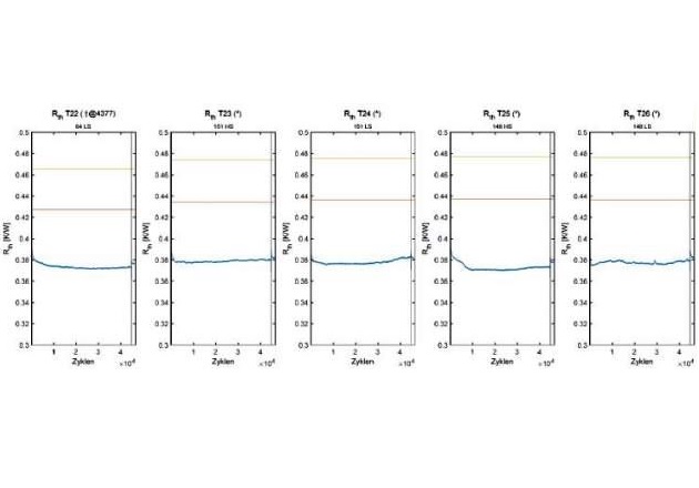
Figure 4: Rth trend (blue) of flow S3 at power cycling minutes test (dT=75 K, ton=30 s, test stopped at 54k cycles)
Figure 5 shows the normalized thermal resistance trend of flow S3 at passive thermal cycling from –40 °C to +125 °C with 30 minutes dwell time at each temperature. The test aperture has two chambers and the mounted modules are moved from one chamber to the other within less than 1 minute. This test is also known as temperature shock. Failure criteria for the passive thermal cycling test is an Rth increase by 20% referenced to the initial value.
From the test results, it can be concluded that the thermal resistance of flow S3 is long-term stable. Neither power cycling minutes nor passive temperature cycling, are able to trigger TIM pump-out, which would be indicated by an increase of thermal resistance.
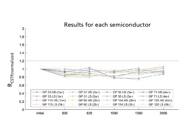
Figure 5: Normalized Rth(j-s) of flow S3 at passive temperature cycling (-40 °C/+125 °C, test stopped at 2k cycles)
Superior Die-Attach Technology for an Increased Lifetime
For validation of the long term reliability of the solder joint, a highly accelerated High-Temperature Forward Bias (HTFB) test is carried out. The HTFB test is performed at nominal chip current and maximum operation junction temperature. The failure mode is the delamination of the solder joint, which yields to increase of the thermal resistance. The failure criteria is an increase in thermal resistance by 20%. After 2700 hours the test was stopped without failure of the advanced die-attach technology. The advanced die-attach technology shows more than 10 times longer lifetime (Figure 6) than standard technology.
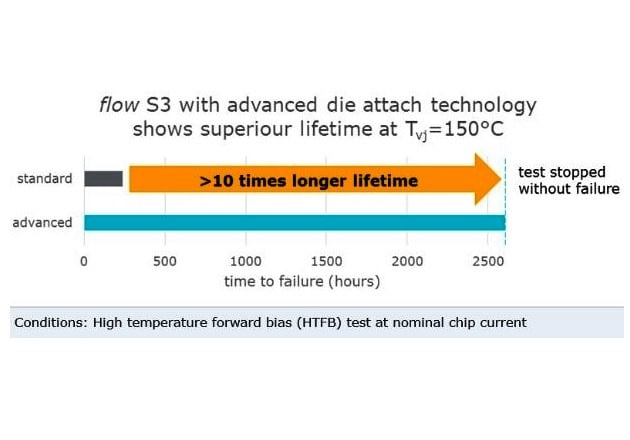
Figure 6: Comparison of time to failure at high temperature forward bias (HTFB) test between standard and advanced die attach technology (test parameters: Itest = In, Tvj = 150 °C)
Applications with mission profiles containing long operation time at high temperatures together with high current benefit directly from the lifetime increase of the advanced solder technology. Those applications are for instance solar inverters with an oversized solar generator.
Application examples
In 1500 V multi-string solar applications the flow S3 housing supports inverter output power beyond 300 kW and fosters the trend to further increase the inverter output power and power density.
For motor drive applications the combination of more ceramic area and lower thermal resistance allows the doubling of the maximum nominal current of 6PACK and PIM configuration in flow S3 to 200 A respectively 100 A (Figure 7). The module power density (kW/cm²) can be increased up to 12% with flow S3.
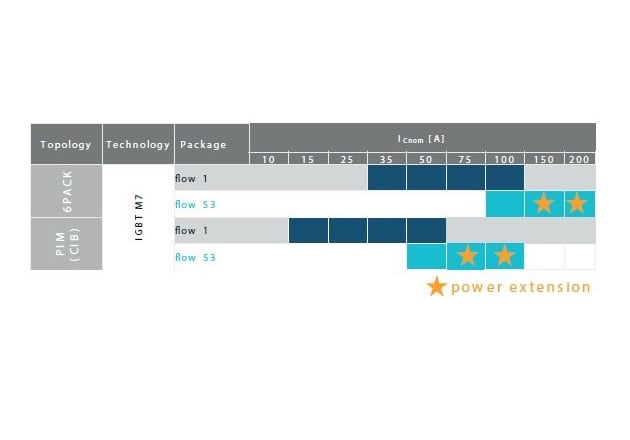
Figure 7: flow S3 allows power extension for 6PACK and PIM
Conclusion
This article introduces the new flow S3 baseplate-less medium power package and highlights the superior thermal performance achieved by high and uniform pressure distribution. The long term stability of Rth is proven by the active power cycling and passive temperature cycling tests. High reliability is also supported by the lifetime increase introduced with the advanced die-attach technology. In summary, the flow of S3 housing is the perfect fit for all applications demanding high power in a small footprint.
This article originally appeared in the Bodo’s Power Systems magazine.
About the Author
Matthias Tauer received his degree in the Field of Electrical and Electronics Engineering at the Technical University of Munich. He worked as a Technical Marketing Manager at Vincotech. Matthias joined Vincotech in 2016 after working as a power electronics R&D engineer for 6+ years, developing solar inverters and resonant dc/dc converters and diving deep into fast-switching semiconductor technologies.