Facebook
 Google
 GitHub
 Linkedin
Small Heat Loads: Big Challenge to Enhance Heat Sink Performance?
This article discusses the optimization of heat sinks to be used in handheld devices particularly on heat sink spacing and thickness.
Within the thermal industry, there is a common belief, that small heat loads are easily dissipated with conventional heat sinks. To a degree, this belief is true, however, when it comes to the optimisation of low power heat sinks, the challenges are as prominent as they are with multi- Kilowatt heatsinks. When dealing with low power heat sinks, performance gains are very hard to achieve and even harder to quantify as they are often only a fraction of a degree.
Columbia-Staver have recently been studying the optimisation of a heat sink to be used in handheld devices. As expected all of these issues were seen first-hand together with some additional project-specific challenges such as maximum skin temperature on the heat sink.
In order to achieve the best possible performance, an approach with multiple prongs was chosen:
-
A new heat sink similar to the current design was selected and a number of physical prototypes were produced. This enabled the customer to progress with his prototype development on a system level.
-
The new heat sink was subjected to a detailed thermal evaluation using CFD. A simple unenhanced aluminium heat sink was the benchmark to be compared with a number of enhancements:
-
The application of three L-Shaped heat pipes.
-
A combination of two heat pipes and a copper insert
-
A novel method which involved the “cold bonding” of copper bases to an Aluminium cold forging
Comparison of these different heat sink enhancement methods showed improvements against the benchmark heat sink, but the improvement increments when compared with the cost implications were seen as not large enough to justify the cost increase.
-
-
The optimisation tool within Ansys ICEPAK was used to optimise both, the fin pitch and the fin thickness on an equal surface area heat sink. This was necessary due to the complex geometry of the device heat sink, which could not be parametrised. These findings were then manually transferred into the customer heat sink with its more complex geometry and individual features for final verification.
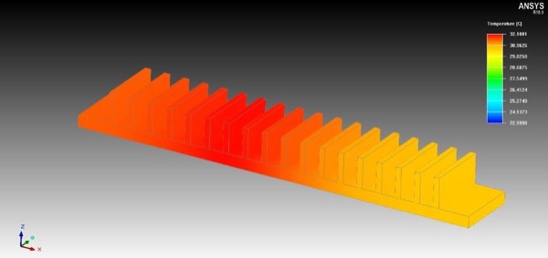
Figure 1: Heat Sink Layout – Equal Surface Area Heat Sink
For this project, and in order to mitigate customer concerns as well as determine the power level the heat sink has to dissipate, the modelling strategy was applied to the existing product and compared against empirically gathered data. This was necessary due to the fact that the heat sink is to dissipate heat loads from a collector, which connects to a number of components within the device.
For a known temperature on top of the collector, which was achieve during testing, it was determined that the heat sink is dissipating 1.2 Watts. Once that power level was obtained, the model was run in fixed power mode, and a comparison of the experimental data with the predicted data was made. For that location on top of the internal heat collector, very good correlations within 0.1°C between simulation results and measurements were achieved. Therefore the model was seen as accurate enough and used for the investigation of the new heat sink.
The new geometry was then benchmarked as just a plain heat sink to ensure that the CFD model is working as intended and producing stable results. Once that was found, different enhancement technologies, such as heat pipes, a combination of heat pipes and copper inserts in the heat input are of the heat sink, and also a novel technology, where Aluminium and Copper were diffusion bonded within the cold forging tool were investigated. Results from this investigation can be found within Figure 2. The figure is reporting the heat sink performance in the form of thermal resistance, to allow the direct comparison between all results and is to be understood that the lower the value, the better the heat sink performance.
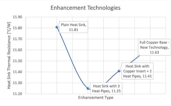
Figure 2: Heat Sink Enhancements Comparison
It can be seen from Figure 2, that all results are reasonably close to each other, but, the version with three L-Shaped heat pipes offers the greatest performance gains. However, when the thermal resistance difference is translated back to a temperature difference, for the power level of 1.2Watts, it would only result in a 0.67°C difference in component temperature between the best-enhanced version and the plain Aluminium heat sink. It has also to be concluded, that in this instance, the novel direct diffusion bonding of Aluminium and copper in the cold forging tool does not offer any significant advantages.
Based on the above findings, further investigations towards optimising the conventional heat sink were undertaken. With the heat transfer mode being natural convection, the first area to investigate was the fin spacing. The initial fin spacing was 5mm, and two different avenues were pursued, first a manual attempt, where the heat sink geometry was changed in CAD and then re-imported into ICEPAK and investigated.
This lead to one curve, however, it was also seen as beneficial to use a more automated optimisation approach through the parametric solver within ICEPAK. In order to be able to use this tool, the heat sink had to be simplified into an equal surface area native ICEPAK smart part. For this, the width and depth of the heat sink were maintained, and the fin height of the rectangular fins was determined by the surface area of the previous heat sink. The collector heat source was applied off-centre directly under the base of the heat sink, and not on a non-finned wing. This simplification has led towards an approximately 1°C difference in component temperature between both models, which needs to be considered when looking at the results. Overall, a range of fin spacings starting at 4mm and ending at 6mm was investigated, and where possible, the results of the analysis of the full heat sink were overlaid onto the graph of the parametric optimisation.
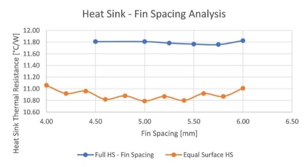
Figure 3: Fin Spacing Comparison
When looking at the above results in Figure 3, a number of factors have to be considered, which contributed to the odd-looking curve being returned from the parametric optimisation. The first one is that the geometric footprint was maintained at all time, meaning that when the fins outgrew the footprint available on the heat sink base, a fin was dropped.
Therefore, the results are a combination between the benefits of an increased fin spacing and a reduction in available fin area, which directly counteract each other. The second factor is that the real heat sink has a number of cut-outs and different fin geometries, which also counteract the trend that a larger fin spacing can show significant benefits.
After it was found that a change in fin spacing alone would not offer a significant performance change, the fin thickness became the next candidate for investigation. Fin thicknesses from 1mm to 3mm were investigated in 0.25mm steps and the results can be seen in Figure 4 below.
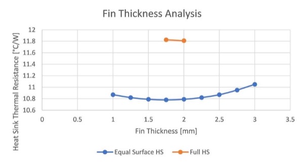
Figure 4: Fin Thickness Comparison
Figure 4 shows that a sweet spot in fin thickness was around the 1.5 – 2mm mark, where the fins are thick enough to conduct the heat away from the base, but not too thick to prevent effective dissipation into the air by acting as a thermal damper. Again, it can be seen that the results are very close together, and the potential performance gains are fairly small. Once the reduced fin thickness was transferred into the CAD geometry of the full heat sink, and investigated in the full model, it was seen that the component temperature was maintained, and a 4% weight saving could be achieved, but no additional performance gains realised.
Overall, it has to be concluded that the optimisation of a low power heat sink has proven quite challenging, and performance gains were hard to achieve and not easy to quantify due to their minute nature. Based on these findings, other factors such as component costs had to be taken into account as well, and carefully be weighed up against any potential gain in thermal performance.
With that in mind, any changes to the initial fin geometry are seen as very beneficial as it comes without any cost penalty. With a conventional optimisation, the component temperature could be maintained but with a weight reduction of 4%. This offers the customer an advantage to his device, but it also again proved the usefulness of CFD as a tool to quickly and cost-effectively evaluate multiple concepts for cooling solutions prior to committing resources to test multiple prototypes. Once all the results are available and evaluated, and combined with the customer’s changed geometry, a final round of prototypes will be produced and then undergo approval testing prior to the official device launch later this year.
For Columbia-Staver, this project was an important milestone to showcase the increased in-house simulation capabilities for the first time and also penetrate an exciting new market, which is for handheld medical devices.
About the Author
Andreas Engelhardt works as a Business Development Manager at Columbia-Staver Ltd.; supporting the diversification of the business towards higher engineering content products. He earned his Dipl. Ing. in European Mechanical Engineering (EMS) at the University of Applied Sciences Osnabrueck. He then acquired his Master of Engineering in Mechanical and Automotive Engineering at the University of Newcastle-upon-Tyne, a public research university located in North East of England. He also then acquired his Doctorate Degree in Built Environment - Engineering at the University of Nottingham in England.
This article originally appeared in the Bodo’s Power Systems magazine.