Facebook
 Google
 GitHub
 Linkedin
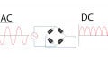
Second Sourcing Rectifiers
This article will focus on some of the issues designers face when comparing datasheets and what critical information is missing in a datasheet.
Billions of rectifiers are produced every year. Because there are not that many technological advances, designers are quite happy to continue using old designs. Supply chain problems or cost savings drive the need for change. This starts with a datasheet comparison. This article will focus on some of the issues designers face when comparing datasheets and what critical information is missing in a datasheet.
Rectifiers are critical components for any manufacturer of power management systems. Although they are usually low in a Pareto analysis of field failures, they are some of the hottest components on the PCB, determine efficiency and EMI, and are exposed to many temperature cycles and high voltages.
Absolute Maximum Ratings
There are only 2 absolute maximum ratings in a rectifier datasheet: the surge current Ifsm and the breakdown voltage Vrrm. Exceeding them may result in catastrophic failures.
The breakdown voltage is 100% tested in production. Most standard rectifiers have many different part names going typically from 100V to 1000V, but they may only have one or two die sources. Different suppliers may have different test specifications, guard bands, and distributions on breakdown voltages. You should be aware of these differences if there are voltage spikes in your design. Having only one wafer source means the electrical characteristics in a forward direction will be the same for all voltages. This information can be helpful in case of supply chain problems.
The Ifsm surge current is not tested in mass production but is guaranteed by design. It is determined by the die size, as the inrush current in AC/DC converters usually is less than 1.5ms. To save costs, different suppliers may reduce their die size. The manufacturing process may produce different amounts of solder voids – which also impacts the surge current. So if your design is marginal on a surge, you may want to do some detailed testing when cross-referencing (surge to failure). Different suppliers may also have different test conventions on delta Vf to eliminate worst case solder voids. A delta Vf test measures the Vf before and after a short current pulse, which heats up the die. The Vf of a rectifier has a negative Tc. The shift in Vf gives an indication of the thermal resistance.
The maximum junction temperature Tj of a rectifier can be interpreted and used in 3 different ways: to determine the current rating, set reliability testing and determine long term reliability using the Arrhenius equation (FIT data at a Tj of 149C are better than at 151C, but neither are good)

Figure 1: Derating-Curve of the Rectifier diode 1N4007
Marketing can influence the maximum Tj in the datasheet. In the case of AECQ qualified devices, reliability testing should be done at the rated temperature and rated voltages. In the case of non-AECQ101 devices, the supplier has more freedom (JEDEC norms – company internal procedures)
Rectifiers are temperature driven devices. The most important equation for a rectifier is Tj = Ta+ Pd*Rthj-a where Tj is the junction temperature, Ta the ambient temperature, Pd the power dissipation, and Rthj-a, the thermal resistance junction to ambient. Usually one can ignore leakage current and switching losses: in that case Pd= If * Vf . Marketing people can influence the current rating of a device.
Marketing determines the Rthj-a in this curve and the point at which the derating starts. The same rectifier can have a current rating x2 under different thermal circumstances. This can be avoided by using case temperature Tc on the x-axis and the Rthj-l is a fixed value in the datasheet. The thermal resistance consists of 2 parts: thermal resistance junction to case/lead and the thermal resistance case / lead to ambient. Unless the products are heatsinked (or very good convection cooling), the latter part of the thermal resistance is the major contributor (75% plus). Derating using Tc then becomes meaningless.
So using current rating as a main parameter when cross-referencing can result in surprises. The statement that a rectifier is 3A or 5A can be misleading. It is better to compare the Vf specifications and test conditions. However two different suppliers may have 2 different Cpk targets. It is best to analyze the typical Vf curve. This curve cannot be manipulated and if measured correctly allows you to compare apples to apples (die sizes).

Figure 2: Typical Vf -curve
Other Electrical Characteristics
Leakage current specifications are set at 1uA to 5uA for standard rectifiers in many datasheets. These datasheets can be 30-50 years old. The normal distribution of the leakage current stops at around 100nA, depending on the die size. Standard rectifiers are manufactured using so-called GPP processes (Glass Passivated Pellet). There are differences in quality between these processes. Sometimes the discussion on a Tj rating of 150 or 175C can be best verified by comparing the typical Ir curves at higher temperatures.
The most important surprises when cross-referencing may come from the different test programs used by various manufacturers. Reliable rectifiers need PAT (Part Average Testing), aligning the test specification on Ir with the normal distribution, not the datasheet value. Parts outside the normal distribution but inside the 1/5uA datasheet limit may have hidden quality problems. Downgrading – retesting rectifiers that do not meet 1000V and selling them eg as 100V at a lower price with a higher leakage current – is a recipe for failure in the field.
PAT uses statistical techniques to establish the limits on these test results. These test limits are set up to remove outliners (parts whose parameters are statistically different from the typical part) and should have minimal yield impact on correctly processed parts from a well-controlled process)

Figure 3: PAT testing eliminates field failures
Recovery Time (Trr): The definition of Trr is based upon mass production test equipment built more than 40 years ago. It may be adequate in applications switching at 40kHz or less and ZCS topologies. In circuits with hard switching, the Trr parameter is not the most important one and the technology differences between suppliers can become apparent. The peak reverse current Irrm adds to the stress of the switching transistor, the Qrr further determines switching losses and softness (Tb/Ta) may be different. A meaningful comparison of 2 datasheets is only possible if the same forward current If and di/dt has been used to turn off the diode. Qrr, Irrm and Tb/Ta are temperature dependent and have a positive temperature coefficient. Datasheets may give an indication of the softness (EMI), but this parameter is also temperature-dependent.
Lower Voltage FER rectifiers can be produced in several different ways. A 200V output rectifier may be produced using Epitaxial wafers or non-EPI wafers. This may result in a lower Vf and a better Trr. There is however a cost penalty. To reduce Trr the supplier will need to add more Platinum or other lifetime killing materials. These tend to increase Vf . So when second sourcing or designing with FER diodes you will need to take this trade-off into account. Every supplier may have a unique recipe.

Figure 4: Avoidance of hot spots through improved lead frame design
Different suppliers of Bridge Rectifiers may have different construction models/lead frames and thermal resistance so the temperature profiles should be checked with an IR camera. More liberty is taken on the die size when manufacturing bridge rectifiers to reduce costs. Make sure to always compare Ifsm. The molding compound used has a big impact on humidity related to reliability testing.
Conclusion
In the case of a conservative design that is well derated, it should be easy to cross-reference standard rectifiers and switch suppliers. If the design is marginal, extensive testing needs to be performed.
About the Author
Jos van Loo is a technical expert for Power Semiconductors for more than 30 years. In his role as Technical Support Engineer at Taiwan Semiconductor Europe GmbH, Jos consults customers on Rectifiers, MOSFETs, and Power Management ICs.
This article originally appeared in the Bodo’s Power Systems magazine.