Facebook
 Google
 GitHub
 Linkedin
Go Differential to Test SwitchMode Power Supplies
On its journey from wall socket to the device being powered, power typically passes through a switch-mode power supply, where the AC signal is rectified
On its journey from wall socket to the device being powered, power typically passes through a switch-mode power supply, where the AC signal is rectified into DC before it reaches the device. After that, the DC signal (often 5 V) is passed on to DC-DC converters on the device's PC board for feeding various voltages to branches of the device's power-delivery network. Let's look at some of the measurement techniques and considerations relative to testing switch-mode power supplies.
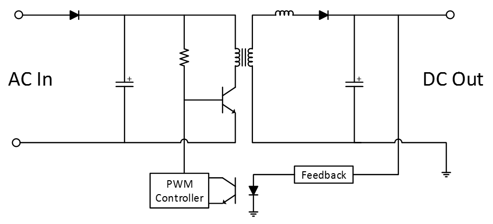
Figure 1. Shown is a basic switch-mode power supply circuit with diode/capacitor rectifier for the AC input on the left, followed by a switching transistor driven by a PWM controller that determines how much DC power is seen on the far side of the transformer.
What does a basic switch-mode power supply circuit look like? In Figure 1, the input side on the left begins with a diode and capacitor that serve to rectify the AC input. That's followed by a switching transistor, typically a MOSFET, driven by a pulse-width-modulation (PWM) controller that determines how much DC power is seen on the far side of the transformer. Some of this signal is fed to an op amp that provides feedback to the PWM modulator so it can properly adjust the DC voltage depending on the load.
A number of measurements are possible on both sides of the transformer. On the input side, which is not referenced to ground, measurements include:
- Inrush current
- Power quality
- Line power
- Switching loss
- Safe operating area
- Control loop
- Dynamic on-resistance
On the ground-referenced output side, the roster of measurements includes:
- Step load response
- Ripple
- Transformer B-H (magnetization)
- Saturation
- Turnoff characteristics
Measuring Voltages
Voltages on switch-mode power supplies present some measurement challenges. They cover a wide dynamic range from millivolts to kilovolts. On the input side, they're not referenced to ground. You have to be concerned with effects of circuit loading. And, it's an inherently noisy environment; that noise can couple into your probe and/or the signal you're trying to measure.
With a general-purpose oscilloscope and the typical 10-MΩ passive probe, here's the issue for measuring voltages: If you want to probe the MOSFET, where do you connect the ground lead? If you have, say, +175 V on one side of VGS and -175 V on the other, you have no true ground. Sure, you could connect ground to one side but that's liable to result in a short circuit. The probe's ground lead is connected to the case of the oscilloscope, which is connected to earth ground by the ground wire in the oscilloscope's power cord (Figure 2). This results in a ground loop that acts like a shorted transformer turn when intercepting any stray magnetic field. Of course, conductors carrying high currents create these fields.

Figure 2. The probe's ground lead is connected to the case of the oscilloscope, which is connected to earth ground by the ground wire in the oscilloscope's power cord. This results in a ground loop that acts like a shorted transformer turn when intercepting any stray magnetic field.
The circulating current in the ground loop creates a voltage across any impedances within the loop. For AC components, the predominating loss element is inductive. The ground lead at the tip of the probe forms an inductor across which the AC components of this voltage appear. Thus, the voltage at the probe input of the oscilloscope is not equal to the voltage at the probe's tip. Oscilloscopes measure the voltage at the BNC connector, not the probe tips.
The answer to the problem is to use a true differential amplifier, which gives you the best measurement quality for signals that are not referenced to ground (Figure 3). The output of the differential amplifier is referenced to ground, so the oscilloscope remains safely grounded. Both of the amplifier's inputs are high impedance, minimizing the effects of capacitive loading on the circuit's operation and on the measurement.

Figure 3. The answer to the ground-loop problem is to use a true differential amplifier, which gives you the best measurement quality for signals that are not referenced to ground.
The differential amplifier takes in the two input signals and subtracts them from each other, which eliminates the need for a ground connection. It also has the benefit of canceling out any common signal on both of the probes (common-mode rejection). Thus, noise coupled from the MOSFET's switching will typically get into both probes and be canceled out. An example of a popular differential amplifier for these kinds of applications is Teledyne LeCroy's DA1855A.