 Facebook
 Google
 GitHub
 Linkedin
EMC Filters Interferencefree converter output
This article discusses the TDK's offer of EPCOS's filters and reactors to reliably eliminate any kind of interference and EMC at the converter output.
EMC problems in frequency converters occur not only at the input, but also at the output. To ensure reliable elimination of any kind of interference at the output as well, TDK offers a wide range of EPCOS filters and reactors.
Frequency converters are used for regulating the speed of asynchronous motors. In applications, in which the converter and motor are connected by a longer cable, parasitic capacitances occur between the conductors and to ground. In addition, the rise time of the square wave pulses of the converter output voltage is in the range from 5 to 10 kV/µs, which causes high-frequency currents in the cable on every switching operation. These have a whole range of negative impacts:
- The superimposition of high-frequency currents on the cable reduces the amount of current available for operating the motor. To compensate for this, the converter must, therefore, be dimensioned for a higher power rating.
- Interference currents on long cables can be so great that the overcurrent protection switch of the converter is tripped.
- High-frequency currents, with their high switching frequency content, cause losses both in the cable and in the motor.
- As a proportion of the high-frequency currents are conducted to ground, they cause asymmetric interference. If unshielded motor cables are used, this would consequently result in inadmissibly high interference fields. For this reason, expensive shielded motor cables are generally used.
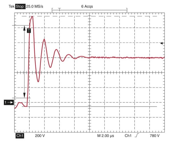
Figure 1: Voltage overshoot caused by motor cable
*Long motor cables exhibit a relatively high inductance and cause large voltage overshoots in the case of steep rising edges.
- Moreover, the steep rising edge of the converter voltage excites parasitic oscillating circuits that consist of cable and motor capacitances as well as line inductances. Their transient characteristics overlay the converter voltage. On the motor side, this primarily results in momentary voltage overshoots which can far exceed the rated motor voltage (Fig. 1) and exert a load on the motor insulation due to partial discharges, which in turn can cause a motor to fail.
Overall, this creates the following problems at the converter output:
- Very high-frequency reactive currents in the motor cable
- EMC problems
- Overvoltage at the motor caused by steep voltage gradient and long motor cable
- Damage to the motor insulation
- Bearing damage due to leakage currents through the motor bearings
- Motor noises
Output filters permit effective interference suppression
For effective interference suppression, essential factors such as cable length, spectrum of interference frequency, motor type, or even rated power, are decisive. The amount of effort actually necessary and reasonable for suppressing interference at the converter outputs must be decided on a case-by-case basis.
dv/dt choke
EPCOS dv/dt chokes, also called motor chokes, are typical components for suppressing interference caused by long motor cables. The entire motor current flows through these serial chokes. Steep current and voltage rise at the output of the frequency converter are evened out by the inductance, while the parasitic capacitances of the motor cable are charged and discharged less powerfully. Motor chokes are used mainly for protecting motor windings against voltage spikes.
The components of Series B86301U* (Figure 2) are designed for a rated voltage of 520 V AC and, depending on type, for current capabilities of between 8 A and 1500 A. They are suitable for motor cables with a length of up to about 100 m at motor frequencies of between 0 Hz and 400 Hz. The smaller series types are designed for a maximum clock speed of 16 kHz or, in the case of versions with current capabilities of higher than 500 A, just 2.5 kHz. The design of the chokes complies with the IEC 60076-6 standard and all series types are manufactured with the UL-approved T-EIS-CF1 insulation system.
Sine-wave filters
If greater demands are made on the interference suppression, sinewave filters are recommended. These are designed as LC filters but, unlike the motor chokes, their limit frequency lies between the output frequency and the frequency converter clock speed.
As the sine-wave filter mainly suppresses the symmetrical interference between the lines, the interference acting on the phase-to-ground voltage is hardly reduced at all. Therefore, the motor leads still require shielding. Sine-wave filters reduce the motor noise and the eddy current losses and permit the use of motor leads much longer than 100 m.

Figure 2: Motor chokes suppress voltage spikes The extensive range of EPCOS motor chokes covers a range of currents from 8 A to 1500 A. These prevent voltage spikes in the motor windings and thereby extend the service life of the motors.
Typical sine-wave filters are the components of the EPCOS B84143V*R227, R229 and R230 series. These are designed for continuous currents of between 4 A and 320 A at rated voltages from 520 V to 690 V and, depending on type, the permissible clock speed of the converters is between 1.8 kHz and 16 kHz.
SineFormer®
Although motor chokes and sine-wave filters reduce voltage peaks on the motor cables, they have barely any effect in the case of interference acting on the phase-to-ground voltage. That’s why shielded motor cables remain a necessity. Moreover, motor bearing currents are hardly reduced with the above measures alone.
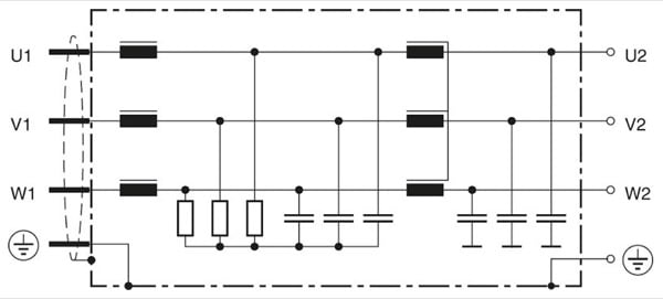
Figure 3: Circuit diagram of EPCOS SineFormer The SineFormer attenuates both symmetrical and asymmetrical interference. This eliminates the need for expensive shielded cables and protects the motor.
In order to reduce the asymmetric interference on the motor cable to such an extent that the cable requires no shielding, it is necessary to use an EMC sine-wave filter, which consists of a sine-wave filter supplemented by a current-compensated choke and capacitors to ground. The EPCOS SineFormer (Figure 3) is based on this circuit design.
Overview of benefits
Technical benefits of the EMC concept with SineFormer
- Reduction of the dv/dt to <500 V/μs
- Reduction of the noise generated by the motor
- Significant reduction of the eddy current losses
- Considerable reduction of the motor bearing currents
- Prevents coupling of interference from the motor cable with other network and signal cables • Better EMC performance than shielded cables
- Radio interference emission within limits specified by standards
- Best possible reduction of the interference (conducted and radiated) in comparison with other output filter solutions
- No feedback to the converter’s DC link is necessary
Economic advantages of the EMC concept with SineFormer
- Unshielded motor cables can be used, enabling installation overheads to be reduced, the service life of the motor to be extended significantly and the costs for motor cables to be minimized
- Motor size can be reduced
- Longer motor cables are possible (up to 1000 m unshielded have been measured) • No maintenance costs, as the SineFormer is designed without any forced ventilation
- Compact filters (no modular system) with reduced volume and weight
- Requirements on the line filters can be reduced
- Increased system availability
- Suitable for retrofitting
The use of SineFormer in combination with unshielded cables is – depending on the cross-section and cable length – usually more economical than the use of shielded cables. In installations with cable lengths of over 100 m the cost savings by using an unshielded cable instead of a shielded cable more than compensates the additional cost of SineFormer. If the costs of the SineFormer and unshielded cable are compared with those of a sine-wave filter and a shielded cable, then the point at which SineFormer represents the more cost-effective solution is already reached at less than 50 m. This does not even take into account the fact that shielded cables incur additional mounting costs.
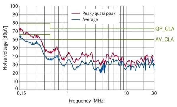
Figure 4: Noise voltage measurement on EPCOS SineFormer. Despite the unshielded cables, the permissible limits are observed.
Figure 4 shows how well the SineFormer technology works: Even when power cables and unshielded motor cables are laid across each other, the limit values are met with a safe margin (in this case according to EN 61800-3 Category C2). The fact that virtually no coupling occurs is proof of the excellent effect of this filter technology. Overall, this enables system costs to be reduced and the plant availability to be increased.
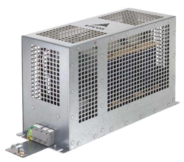
Figure 5: B84143V*R127 SineFormer
| Rated Voltage | 520VAC up to 180A, 600VAC (320A) |
| Rated Current | 6A to 320A |
| Converter Pulse Frequency | 4kHz to 8kHz up to 180A; 2.5kHz to 3kHz at 320A |
| Approvals | UL and cUL up to 180 A (except 6A and 45A) |
Table 1: Technical parameters of the EPCOS SineFormer
B84143V*R127 SineFormers are also suitable for retrofitting – i.e. when EMC problems caused by the motor cable do not become apparent until the drive is put into service. Attention should still be paid in every case to the suitable design of the line-side EMC filter, e.g. with the aid of the new compact B84243A* series of line filters. Limit Class C2 can be achieved according to EN 61800-3 in combination with SineFormer and with unshielded cables up to 300 m.
About the Author
Carsten Juergens works as the Director of Product Marketing for Power EMC Filters at EPCOS Inc., a TDK Group Company, Iselin, NJ.
This article originally appeared in the Bodo’s Power Systems magazine.


