Facebook
 Google
 GitHub
 Linkedin
Dissecting Electric Motor Malfunctions
Learn about the important electric motor parameters, such as voltage rating, acceleration time, overcycling, and insulation resistance, that should be taken into account to avoid electric motor malfunctions.
Electric motors are designed and sized to operate in HVAC systems for a number of years with minimal malfunctions or failures. For a motor to operate without malfunctions or failures, the motor electrical operating conditions must be within the original equipment manufacturer (OEM) operating specifications.
The motor operating specifications are listed on the motor nameplate. Motors are rated to operate at a specified voltage and current to deliver full horsepower without producing excessively high temperatures. In addition to the voltage being within the acceptable range of the nameplate rating, high transient voltages must be avoided because they can cause deterioration of motor insulation and electrical malfunctions.
Voltage Malfunctions
Electric motors have an operating voltage range in which they can perform satisfactorily. The OEM specifies the operating voltage range in the electrical specifications provided with the HVAC system or motor. It is standard practice to use the OEM specifications because the listed values are based on data from actual motor use and operating conditions. If OEM specifications are not available, the voltage range is normally +5% to –10% of the nameplate rated voltage (see Table 1).
| Nameplate Rated Voltage (V) | Min. Voltage (V) | Max. Voltage (V) |
| 230 | 207 | 242 |
| 460 | 414 | 483 |
Table 1. If original equipment manufacturer (OEM) specifications are not available, the motor operating voltage range is normally +5% to –10% of the nameplate rated voltage.
When measuring voltage, it is best to measure the voltage over time. A test instrument MIN MAX operating function can be used. Voltage measurements taken overtime should not vary by more than 3%. A high voltage fluctuation is an indication that the system is overloaded, the conductors connecting the system are too small, or the conductor run is too long.
For three-phase motors, the voltage between each of the power lines connected to the motor (T1 to T2, T2 to T3, and T1 to T3) should be measured. The voltage measured between any two lines should not vary more than 3%.
Excessive Heat Due to Motor Acceleration Time
When full power is applied to a motor, the motor accelerates to full speed. When a motor starter is used to start a motor, the motor must accelerate to its rated speed within a limited time period. The longer the time it takes the motor to accelerate,the higher the temperature rises in the motor. The greater the load under which a motor must operate, the longer the acceleration time. The maximum suggested acceleration time is determined by the size of the motor frame. Heat is dissipated faster by large motor frames than by small motor frames.
When a motor drive is used to control a motor, acceleration and deceleration time can be programmed to best match the requirements of the application. The programmed acceleration and deceleration time must not overheat the motor. Motor drives automatically control the voltage applied to a motor to keep it from overheating at all speeds. However, in HVAC systems, the motor acceleration time should be as short as possible. Normally, the OEM default settings for acceleration and deceleration times are acceptable (see Table 2).
| Frame Number | Max. Acceleration Time (seconds) |
| 48 and 56 | 8 |
| 143-286 | 10 |
| 324-326 | 12 |
| 364-506 |
15 |
| Parameter | Min. Max. Setting (seconds) | Factory Default Setting (seconds) |
| Acceleration Time | 0.1 – 600 | 10.0 |
| Deceleration Time | 0.1 – 600 | 10.0 |
Table 2. In HVAC systems, motor acceleration time should be as short as possible.
Overcycling
Overcycling is the procedure of repeatedly turning a motor on and off. Overcycling occurs when a motor is at its operating temperature and continues to cycle on and off. Starting current is several times the running full-load current (FLC) of the motor. Regardless if a motor is started using a motor starter or motor drive, most motors are not designed to start more than 10 times per hour because it increases the temperature of the motor, which destroys the motor wire insulation.
Overcycling in HVAC units occurs when the controlling temperature switch (thermostat) differential is set too low. The differential is the difference between the temperature at which a switch turns on a unit and the temperature at which it turns off the unit. For example, a 1°F differential keeps the temperature in a room within 1°F but requires the unit to continuously cycle on and off. Thermostats have a typical default differential setting of approximately 6°F (4.5°C).
When a motor application needs a motor to be cycled frequently, the following guidelines should be applied:
• Install a motor that has a 122°F (50°C) ambient temperature rating rather than a standard 104°F (40°C) rating.
• Install a motor with a service factor of 1.25 or 1.35 rather than a service factor of 1.00 or 1.15.
• Provide extra cooling by forcing air over the motor.
• Install a motor drive to control the motor so the motor speed can be controlled instead of cycling the motor fully on and off.
Note:
The National Electrical Manufacturers Association (NEMA) standard MG1 sets the basic requirements for information to be marked on electric motor nameplates.
Motor Insulation Failure
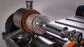
An ohmmeter is a test instrument that measures resistance. A megohmmeter is a high-resistance ohmmeter used to measure insulation deterioration on conductors by measuring high resistance values using high-voltage test conditions. A megohmmeter can detect motor insulation deterioration before a motor fails. Typical test voltages range from 50 V to 5000 V. A megohmmeter is used to measure the condition of motor wiring by detecting insulation failure caused by excessive moisture, dirt, heat, cold, corrosive vapors, or solids, vibration, and aging (see figure 1).

Figure 1. A megohmmeter is used to perform tests on motor insulation.
A megohmmeter is used to measure the resistance of different motor windings or the resistance from a motor winding to the ground. Several test measurements should be taken and recorded over time to provide a complete analysis of the insulation condition. The minimum acceptable insulation resistance depends on the motor voltage rating (table 3).
| Motor Nameplate Rated Voltage (V) | Minimum Acceptable Resistance (Ohms) |
| <208 | 100,000 |
| 208-240 | 200,000 |
| 241-600 | 300,000 |
| 601-1000 | 1,000,000 |
Table 3. The minimum acceptable insulation resistance of an electric motor depends on the motor voltage rating.
Note:
A motor with good insulation may have readings 10 times to 100 times the minimum acceptable resistance. Service the motor if the resistance reading is less than the minimum value.
Cautionary Note:
A megohmmeter uses high voltage for testing (up to 5000V). Avoid touching the meter that leads to the motor frame. Always follow the OEM recommended service and safety procedures. After performing insulation test measurements, connect the motor windings to the ground through a 5 kΩ, 5 W resistor. The motor winding must be connected to the ground for 10 times the motor testing time in order to discharge the energy stored in the wiring.
Related Content