Facebook
 Google
 GitHub
 Linkedin
Clamp-On Ammeter Applications and Measurement Procedures
A clamp-on ammeter is a portable test instrument that measures current in a circuit by measuring the magnetic field's strength around a single conductor.
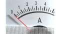
Clamp-on ammeters are used to measure current in a circuit with over 1 A of current and in applications where the ammeter's jaws can easily be placed around one of the conductors. Voltage and resistance can also be measured by most clamp-on ammeters. In order to measure voltage and resistance, there must be test leads and a voltage and resistance mode on the clamp-on ammeter. In addition to basic measuring functions (current, voltage, and resistance), some ammeters also include special functions such as a hold button (HOLD) for maintaining a displayed measurement, a min/max button (MIN MAX) for recording the minimum and maximum measured values, and other special functions (see Figure 1).

Figure 1. Clamp-on ammeters measure current in a circuit by measuring the strength of the magnetic field around a single conductor.
Clamp-on Ammeter Applications
Current is a common troubleshooting measurement because only a current measurement can be used by an electrician to determine how much a circuit is loaded (or working). Current measurements vary because current can vary at different points in parallel or series-parallel circuits. Current in series circuits is constant throughout the circuit. When parallel loads are added to a circuit, the supply voltage remains the same, but the current must increase with each load added.
The largest amount of current in a parallel circuit is at the point closest to the power source. Moving away from the power source, the current decreases as the system distributes current to each of the parallel loads. On an individual leg of a series-parallel circuit, the current going to a load (motor, heating element, or light bulb) is the same as the current on the return line from the load. A slight measured difference—up to 10%—between lines (supply and return) is possible when using a clamp-on ammeter because of the placement of the meter or when low current measurements are taken on high ammeter ranges (measuring 2 A on a 400 A setting). Any variation that is excessive must be investigated because the current measurement may indicate that a partial short exists on one of the lines and the current is flowing to the ground.
Calculating Current Using Ohm's Law
Ohm's law states that the current (/) in a circuit is equal to the voltage (V) divided by resistance (R). To calculate current using Ohm's law, apply the formula:
\[I={}^{V}/{}_{R}\]
where
\(I= current (in A)\)
\(V = voltage (in V)\)
\(R = resistance (in Ω)\)
Example: What is the current through a wire when the wire has 5750 Ω of resistance and 115 V is applied?
\[I={}^{V}/{}_{R}={}^{115}/{}_{5750}=0.020A=20\text{ }mA\]
When measuring current along a circuit that feeds several loads, the current may not be the same on each line. When current measurements are taken at the main power panel or from an electric motor drive, the current on the hot and neutral conductors of a 115 V or 208 V single-phase circuit, and all three phases of a 3(ϕ) circuit, should basically be the same. See Figure 2.
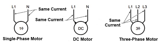
Figure 2. Single-phase and DC circuit current readings should be the same on supply and return wires. Three-phase circuit current readings should be the same on each line (L1, L2, and L3).
Clamp-on Ammeter Measurement Procedures
Clamp-on ammeters measure current in a circuit by measuring the strength of the magnetic field around a single conductor. In order to prevent clamp-on ammeters from picking up stray magnetic fields during testing, electricians must separate the conductors being tested from other conductors as much as possible. When stray magnetic fields may be affecting a measurement, it is necessary to take several measurements along a conductor at different locations. See Figure 3.
Figure 3. When stray magnetic fields are possibly affecting a measurement it is necessary to take several measurements along a conductor at different locations.
If you plan to measure AC or DC current with a clamp-on ammeter or multimeter that has clamp-on current probes attached to it, make sure you follow standard procedures.
Before taking any current measurements using a clamp-on ammeter, ensure the meter is designed to take measurements on the circuit being tested. Refer to the operating manual of the test installment for all measuring precautions, limitations, and procedures. Always wear required personal protective equipment and follow all safety rules when taking the measurement. To take a current measurement with a clamp-on ammeter, apply the following procedures:
1. Determine if the current in the circuit to be measured is AC or DC.
2. Choose a suitable clamp-on ammeter to measure the circuit current (DC or AC). When both AC and DC measurements are required, select an ammeter that can measure both AC and DC current.
3. Ensure that the current range of the clamp-on ammeter is high enough to measure the maximum current that exists in the circuit being tested.
4. Set the clamp-on ammeter function switch to the highest current range (600 A, 200 A, 10 A, or 400 mA). Select a setting as high as or higher than the highest possible circuit current when there is more than one test position or if the circuit current is unknown.
5. Open the clamp-on meter or probe accessory jaws by pressing against the trigger.
6. Enclose one conductor in the center of the jaws. Before taking any current measurements, make sure the jaws are completely closed.
7. Read the current measurement displayed on the clamp-on ammeter or multimeter with the clamp-on probe accessory.
8. Remove the clamp-on ammeter or clamp-on accessory from the circuit.
Technical Tip
Clamp-on ammeters are typically used where voltages are less than 600 V with a frequency under 2kHz.