Facebook
 Google
 GitHub
 Linkedin
Advancing EV Charger Controls: The Role of C-HIL and Dual Active Bridges
This article examines the role of controller hardware-in-the-loop, or signal-HIL, in the design, testing, and manufacture of electric vehicles.
This article is published by EEPower as part of an exclusive digital content partnership with Bodo’s Power Systems.
Transportation electrification is transforming how vehicles are designed, tested, and manufactured. Controller hardware-in-the-loop (C-HIL), also known as signal-HIL, has become an alternative methodology for testing power electronics controls firmware, offering ease of use, wide test coverage through automation, along with relatively low cost compared to testing methodologies that include power flow, such as power-HIL setups.
As the adoption of electric vehicles accelerates, both stationary and on-board chargers (OBC) are gaining increased attention in the industry, presenting challenges critical to the future of electric mobility. To support the development and testing of cutting-edge EV charger controls using C-HIL, the high-switching-frequency power converters typical of these applications must be simulated in real-time with high fidelity. This article provides an overview of the challenges and key solutions that make this possible in an accurate, safe, and cost-effective way.

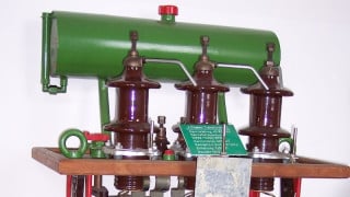
Image used courtesy of Bodo’s Power Systems [PDF]
Real-Time Simulation of Power Electronics
The simulation of power electronics circuits in real-time is typically executed on FPGA-based simulators. When designing such FPGA-based platforms, consider three key aspects:
- Switch model complexity: The semiconductor switch model can be simulated with various levels of fidelity, ranging from highly detailed transient models used for hardware design to ideal switch models or even average converter models that replace the switches with equivalent sources.
- Achievable time step: Depending on the switch model’s complexity, different time steps are necessary to properly simulate all dynamics of interest. Highly detailed simulations of parasitic effects in transient models might require picosecond resolution, while average converter models could be simulated with one simulation step per switching period.
- Ease of use: Maximum performance can be achieved by manually coding and optimizing the equations for the desired converter in VHDL. However, modifying such an optimized model would be very time-consuming and challenging. In contrast, a more generalized simulation approach may lack the optimization needed to achieve the short time steps required.
The main challenge in developing an effective HIL simulator platform is balancing these three requirements. The Typhoon HIL platform is specifically designed for power electronics applications through the following design choices:
- Graphical schematic editor: Graphical schematic editor is used to design the circuit. Instead of generating VHDL code, along with synthesis, bitstream generation, etc., a configurable FPGA solver is used. The model is loaded to the solver via a single-click compilation process, typically taking less than a minute.
- Ideal switch model: Unlike highly detailed switch models, an ideal switch model does not require sub-nanosecond time steps to simulate switch commutation. However, it is still capable of simulating power electronics converters with high fidelity for control design and testing. Different sets of state-space matrices are used to simulate the circuits corresponding to different combinations of switch states. This means a switching event can be simulated by two consecutive time steps with two different matrix sets. The ideal switch model can easily be enhanced by adding a forward voltage drop.
- GDS oversampling: Gate-driving signals (GDS) at the digital inputs of HIL simulators are sampled faster than the simulation time step. Since the controller clock is not synchronized with the simulator, the edge of the gating signal occurs within the duration of the simulation time step. This edge (the switching event) is timestamped, and the information is used to compensate for the simulation results in the upcoming time steps, thus increasing the resolution of switching event detection.
Typhoon HIL simulators have been successfully applied in various power electronics applications for over a decade, with the latest generation capable of simulating circuits with time steps as low as 200 ns and a DI sampling resolution of 3.5 ns.
DC-DC Converter Simulation
A typical EV charger consists of an input power factor correction (PFC) stage and an isolated DC-DC stage, the latter one typically built using a dual active bridge (DAB) or resonant (LLC, CLLLC) converter topologies. Real-time simulation of these DC-DC topologies is especially demanding due to:
- High switching frequencies: These are typically used to reduce the size and weight of high-frequency transformers, which is especially important in OBC applications due to volume and weight constraints. Today, switching frequencies in excess of 100 kHz are common, usually achieved using wide-bandgap semiconductors.
- Power transfer at the switching frequency: In grid-tied converters and electric drive applications, the main power transfer occurs at a frequency at least an order of magnitude lower than the switching frequency. In the case of converters with a high-frequency transformer, such as DAB and LLC converters, power transfer happens at the switching frequency. This means that even a small loss of time resolution will directly affect the power transfer, thus impacting the model fidelity and, consequentially, the controller operation.
Interestingly, the primary source of time resolution loss for DAB and LLC topologies is neither the simulation time step nor the digital inputs sampling resolution. Instead, it stems from detecting diode current zero-crossing, as this type of switching event is typically detected at the time step resolution in real-time applications. This is illustrated by running a DAB converter switching at 100 kHz with a dead time of 2%, with the simulation time step intentionally set to a relatively long 500 ns. As shown in Figure 1, the simulation results are well aligned with the reference power transfer curve at most operating points. However, at certain points, there are significant deviations from the reference. These are the operating points where the winding current crosses zero during the dead time.
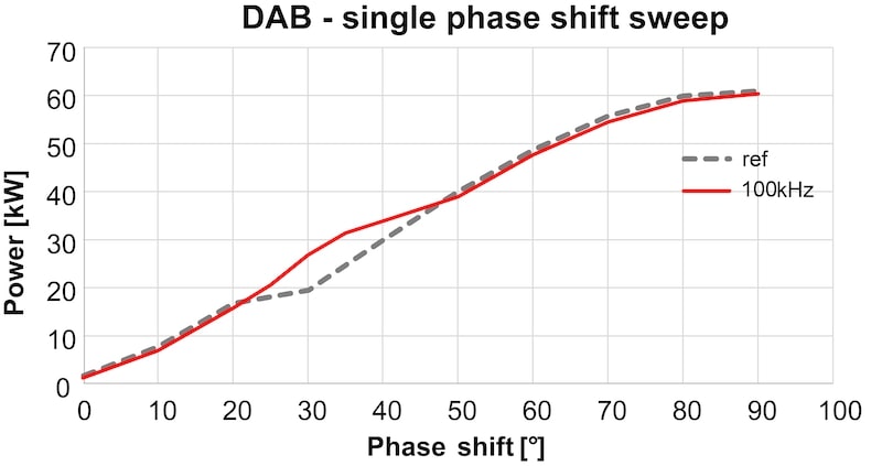
Figure 1. DAB simulation – 100 kHz switching frequency, 500 ns time step. Image used courtesy of Bodo’s Power Systems [PDF]
Through collaborative investigations with industrial partners, Typhoon HIL concluded that DAB and LLC models running with time steps as low as 200 ns still do not provide sufficient fidelity for HIL testing. To improve the diode current zero-crossing detection in these models, a specialized solver has been developed.
DC-DC Converter Solver
The DC-DC converter solver is an optimized FPGA module capable of simulating the DAB and LLC family of converters at a 25 ns time step. This enables a multi-rate simulation with two simulation rates:
- Simulation time step used by a configurable FPGA solver, with the time step down to 200 ns.
- Solver step used by the specialized DC-DC converter solver, which simulates the DAB or LLC models at 25 ns.
These two parts of the model exchange the DC voltages and currents. From the user’s perspective, the solver is deployed as a single component – DAB or resonant converter, which can be adapted for different topology variants, such as CLLLC. This ensures ease of use while significantly improving simulation fidelity (Figure 2).
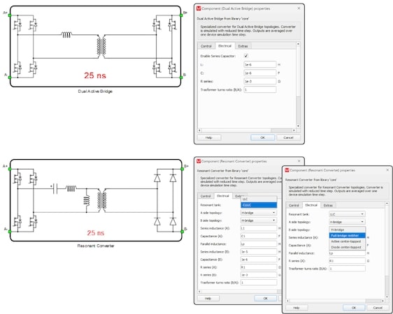
Figure 2. Dual Active Bridge and Resonant Converter Components in Schematic Editor. Image used courtesy of Bodo’s Power Systems [PDF]
To test the performance of this specialized solver, an experimental setup was created using an external controller to replicate a realistic scenario in which the controller clock is not synchronized with the simulator’s time base. The test was initially performed on a DAB converter model, with the results shown in Figure 2. Power transfer was observed as output. Various modulation strategies were implemented to cover various operating points across the entire operational range, including the operating points with diode current zero-crossing events. More detailed data can be found in the white paper published by Typhoon HIL. Results indicate that the simulation performs well for switching frequencies up to 300 kHz.
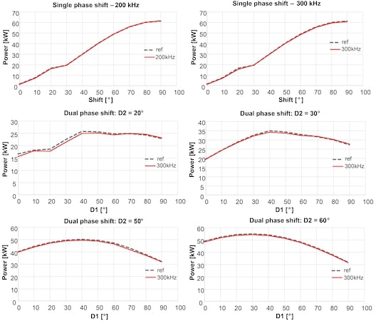
Figure 3. Dual Active Bridge simulation results. Image used courtesy of Bodo’s Power Systems [PDF]
Subsequently, several LLC resonant converter designs were tested, considering a series resonant frequency fr = 250 kHz. The switching frequency was varied from 0.5 fr, up to 2 fr and the output-to-input voltage ratio was used as a benchmark. The parallel-to-series inductance ratio was kept constant (k = Lp ⁄ Ls = 8). At the same time, the characteristic impedance (Zc= √(Ls ⁄ C) was varied, leading to different Q-factor values and voltage characteristics, as shown in Figure 4. Simulation data shows that the simulation performs well in the full range of switching frequencies, up to 500 kHz.
In addition to high performance, resource utilization was also considered when the DC-DC converter solver was designed. As a result, up to 8 converters can be simulated on a single HIL606 device.
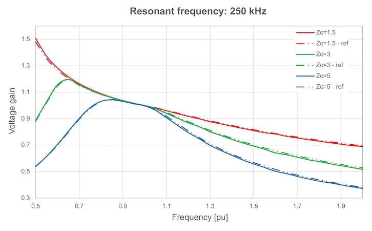
Figure 4. Voltage gain curves of LLC converter. Image used courtesy of Bodo’s Power Systems [PDF]
Takeaways
Accurate real-time simulation of fast-switching DAB and resonant topologies has proven to be a challenging task in practice. The presented optimized solver approach by Typhoon HIL addresses these challenges by providing high simulation fidelity in a wide range of typical applications while maintaining the ease of use typical for offline simulation platforms. Models based on the DC-DC solver have been successfully used for the development and testing of controls in advanced charging applications since 2022. In addition to the results provided in this article, more data can be provided on request, including benchmarking based on a specified set of parameters.
This article originally appeared in Bodo’s Power Systems [PDF] magazine and is co-authored by Jovan Zelic, Senior Modeling Engineer, Dusan Majstorovic, Chief Technology Officer, and Caio Osorio, Applications Engineer & Global Manager, Academia Programs, with Typhoon HIL.