Facebook
 Google
 GitHub
 Linkedin
11 Technical FAQs About the Danfoss DCMTechnology Platform for Automotive Traction Inverters
This article features Danfoss Silicon Power GmbH DCM™Technology Platform for Automotive Traction Inverters that covers an interview with Alexander Streibel.
Curious about the technical details of Danfoss’ DCM™ power module technology platform? Wait no longer. Our application engineers have collected the 11 most frequently asked questions from customers – and we have decided to share with you.
For decades, Danfoss has been helping top-tier automotive manufacturers meet stringent reliability, design and cost targets by developing customized IGBT and SiC power modules for automotive traction applications. With the recent launch of the new Danfoss DCM™ power module technology platform for automotive traction, Danfoss has naturally been invited to pitch to the top-tier automotive players within HEV/EV drivetrain design.
Based on our presentations and technical discussions with customers, we have collected the 11 most frequently asked technical questions about the DCM™ platform. In the following section Alexander Streibel and Arne Bieler, both application engineers at Danfoss, will provide the answers that you have been looking for.
Q: What is meant by the given current rating of DCM™ modules?
Arne Bieler: First of all, DCM™1000 refers to a package size offering footprint to assemble a semiconductor area of 1000mm². Second, current ratings strongly depend on applied boundary conditions such as cooling parameters and DC-link voltage. The current rating for the DCM™1000 considers nominal operation points at customers' side.
Q: Is DCM™ 1000 scalable for several power classes?
Arne Bieler: Adjusting both chip content and DBC substrate materials, we are able to offer several power classes within the DCM™1000 package. This allows customers to use power modules having the same outer dimensions for traction inverters with different output power without the need for a redesign of mechanical components such as cooler. This accounts for both DCM™1000 (750V) and DCM™1000X (1200V). The suffix “X” stands for the extended clearance and creepage distances for applications with up to 1000V DC link voltage. Nevertheless, both the DCM™1000 and DCM™1000X can utilize Silicon Carbide MOSFETs with 800V+ DC link voltage.
Q: Which semiconductors are inside the DCM™?
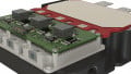
Alexander Streibel: The DCM™ is a technology platform which means that all types of automotive qualified semiconductors can be housed. For 400V and 800V drive train inverters, typically Si IGBTs


Figure 1: Open DCM™ power module with DBB®.
and SiC MOSFETs can be assembled. It is possible to use advanced bonding and joining technologies such as DBB® with either copper wire bonds or copper ribbon bonds.
Q: How do differences between chip suppliers challenge the inverter design?
Arne Bieler: Danfoss has a unique business model and one of the main pillars is chip independency. This means that we are free in the choice of power semiconductors. Of course, even if designed for the same power class, semiconductors from different manufacturers vary in terms of e.g. internal gate resistor, gate charge or even breakdown voltage. For many suppliers, this can challenge the design of the inverter. However, we have thoroughly assessed the differences and can fully support customers during the design of the inverter and the driver board when it comes to a change of the favored semiconductor manufacturer or if a multi source approach is needed. In addition, the low module stray inductance of below 7nH allows the usage of different semiconductors with various breakdown voltages.
Q: How can the modules be mounted? Are there different options?
Alexander Streibel: The modules can be mounted to the cooler by using clamping brackets screwed directly to the cooler. The brackets have direct contact to the available area at the top of the baseplate, shown in Figure 2. There are different concepts available that can apply sufficient pressure for the sealing gasket located close to the borders of each half-bridge.
Danfoss proposes concepts with either two M4 screws or just one M5 screw on each side of the power module. In advanced designs using an aluminum cooler, the total number of screws can be reduced to 4 instead of 8 in typical 6-in-1 module designs.

Figure 2: DCM™ module incl. ShowerPower®3D baseplate screwed to bathtub.
Q: How does the cooling concept work?
Arne Bieler: The cooling concept of DCM™ platform utilizes the patented ShowerPower®3D cooling technology. The baseplate of the power module has meandering channels guiding the coolant and creating powerful swirl effects that washes the boundary layers away thereby maximizing the cooling efficiency. In spite of the swirl effect, the flow is laminar therefore the pressure drop is very low and mainly influenced by the design of cooler in- and outlet and the bypass across the structured baseplate. The final thermal resistance relates to the selected power class, i.e. silicon area and substrate material. The customer designs the bathtub of his cooler according


Figure 3: The bypass creates a flow transverse to the flow direction in the meandering channels thereby amplifying the swirl effect.
to the interface needed for the DCM™1000 power modules. Danfoss can provide all necessary drawings and a reference design from our application-kit.
Q: What is the difference between ShowerPower® and Pin-Fin cooling technology?
Alexander Streibel: The main difference is that with ShowerPower®the power modules are cooled in parallel. This leads to minimized temperature gradient across each half-bridge determining the required derating of the whole system and the overall performance. Parallel cooling offers typically a lower system pressure drop, but the cooler design constraints must be considered for a fair comparison. Considering equal mechanical boundaries for typical cooler designs, e.g. comparing at the same volume and same design guidelines, with ShowerPower®, the same Rth as conventional pin-fin structured baseplates can be achieved at much lower pressure drop.
Q: What is the main difference between molded modules and frame-based modules?
Alexander Streibel: Transfer molding technology is a well-known technology for small-scale high-volume components. However, in Danfoss this technique has been developed over 15 years for large-scale high-power components tailored for high-volume automotive drive train applications in terms of electrical and mechanical ruggedness, ease-of-use and vibration requirements. Terminals are customizable, and the used material is tailored for low tolerance requirements. In sum, the robustness of molded packaging technology has over time proven to withstand harsh automotive conditions and therefore is the preferred choice of Danfoss’ customers.

Figure 4: Visualization of the parallel flow of the coolant.

Figure 5: DCM™ power module with ShowerPower

Figure 6: DCM™ power module with transfer molding
Q: Looking at the connection between the power terminals and dc-link: Are there alternatives to screwing?
Alexander Streibel: We have customers requesting advanced options to minimize the electrical and thermal resistance between the power terminals and the DC link capacitors. We help realize this by e.g. offering a design for resistance or laser-welding methods eliminating any screws.
Q: Can customers get modified terminal and control-pin configurations?
Alexander Streibel: Customers can freely choose between a variety of assembly types for the control pins and terminals to fulfill specific reliability requirements while focusing on total cost of ownership.
The most common types are soldered or press-fit assemblies. Nevertheless, tailored control pins of the power module can solve the bottleneck issues of automotive vibration profiles and assembly tolerances and thus be of great value.
In addition to customized control pins and terminals, the DCM™1000 is truly a technology platform designed for full customization while utilizing our winning technologies. For the customer, this means that Danfoss can support innovative types of inverter designs with our mechanically flexible power modules based on the DCM™1000 technology platform.
Figure 7: DCM™ application kit
Q: When can we get started with the DCM™ platform?
Arne Bieler: During early development of a traction inverter, customers will need a complete package of materials for designing purposes and to assess the performance of the power module during operation. Therefore, Danfoss provides datasheets, CAD files of the module, drawings including the interface to the cooler and detailed application notes.
To make testing fast and easy, we offer an application-kit including DC-link capacitor, driver-board and cooling, providing the possibility to directly test the DCM™ 1000 modules in the laboratory.
Additionally, Danfoss will be present at the yearly PCIM Europe in Nurnberg 7-9 May 2019. Our applications experts will be ready to further discuss the opportunities of the new Danfoss DCM™ platform for automotive traction inverters. Find us at our booth in Hall 9 booth no. 321.
About the Authors
Alexander Streibel works at Danfoss Silicon Power as an Application Engineer. He is responsible for automotive and industrial customer's requests; sales support including design, layout and simulation of power module concepts and lifetime requirements; evaluation of upcoming semiconductor technologies and supplier portfolios; investigation about new cooling concepts; silicon carbide power MOSFET packaging; and transfer of knowledge. He is particularly skilled in power electronics, FPGA, and programming. He earned his Bachelor's Degree in Electrical Engineering at Technical University Carolo-Wilhelmina of Braunschweig. He then acquired his Master's Degree in Mechatronics at the University of Southern Denmark located in Odense, Denmark.
Arne Bieler received his Master of Science in Electrical Engineering and Economics from University of Kiel. He worked as an application engineer at Danfoss Silicon Power GmbH.
Martin Kristensen is a strategic marketing consultant at Danfoss Silicon Power. He holds a B.Sc in international business and an MSc in economics and business administration from University of Southern Denmark.