Facebook
 Google
 GitHub
 Linkedin
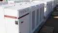
2.5A Supercapacitor Backup Power Manager Demo Board
Demonstration board DC2642A from Analog Devices shows the LTC4041 supercapacitor backup power manager operating with either a stack of two series supercapacitors (DC2642A-A) or a single supercapacitor (DC2642A-B). The board demonstrates the design of a 5V rail with a short-term power backup using 10F supercapacitors.
The input current limit, charge current limit, charge voltage, power fail threshold, and boost voltage are all configurable through changing resistor values on the board. Test points for all monitoring pins and LED indicators on status pins are also available to assist in the evaluation.
Because the LTC4041's power fail function monitors the input voltage to determine its operation mode, it is important to use low-impedance connections to the demo board. Poor quality or lengthy wiring to DCIN can result in a substantial voltage drop across the wires as the DC2642A passes power to the load or charges the supercapacitor(s), leading to undesired triggering of the power fail threshold, 4.7V default.
Short, high-conductivity wires with a good connection are desirable and will mitigate this issue. As a workaround, the power fail threshold can be lowered or a higher voltage can be output from the power source to account for these drops, but this should not exceed the 5.5V rating of the DC2642A.
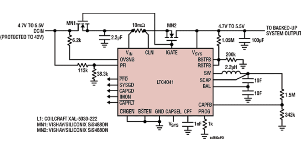 DC2642A schematic (click on schematic to enlarge)
Number of Supercapacitors
The LTC4041 can support either one or two supercapacitors. For safety reasons, DC2642A is broken into two variants: DC2642A-A has two supercapacitors and balancing enabled, while DC2642A-B has one supercapacitor and has no need for balancing.
The LTC4041 uses the CAPSEL pin to determine whether one or two supercapacitors are present and whether balancing should be enabled. The charger also features supercapacitor over-voltage protection, and the voltage limits are based on the number of supercapacitors present as indicated by CAPSEL.
Backup Time
The amount of time that the supercapacitor can back up the system is influenced by many factors. The most prevalent are the supercapacitor voltage, the system boost voltage, and the system load current.
However, other factors such as supercapacitor leakage and ESR can also play a significant role under some circumstances. An equation for estimating backup time is given in the LTC4041 data sheet, but it is still necessary to test operation with given values and components.
The backup time decreases as the load current increases, as expected. However, the decline in backup time is accelerated due to several of the aforementioned factors.
When using a single supercapacitor, the lower voltage limit of the supercapacitor and the fixed boost converter switch current of the LTC4041 will result in a shorter backup time when compared to two supercapacitors stacked in series.
Switch Current Limit
At higher load currents with lower supercapacitor voltages, the LTC4041 will need to limit the supercapacitor's discharge current as to not exceed the current limit of its internal boost switch. This protects the IC, but VSYS will begin to collapse when the switch current limit is reached due to power-limiting.
Equivalent Series Resistance (ESR)
All supercapacitors have ESR which dissipates power and causes a voltage drop when they are being discharged. At lower supercapacitor voltages, the switch limit will be reached sooner, causing a faster collapse of VSYS. For this reason, it is beneficial to select supercapacitors with low ESR. The 10F supercapacitors used on the DC2642A have a typical ESR of 20mΩ.
In the graph below, it can be observed that the dropout voltage for dual supercapacitors (in series) is greater than the dropout voltage for a single supercapacitor. This is because the ESR is greater for series-connected capacitors.
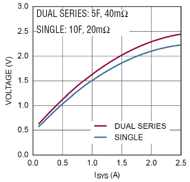 SCAP Voltage at VSYS Dropout for Single/Dual 10F Supercapacitors (Boost to 5V)
The above graph the voltage of the supercapacitor(s) at different VSYS loads after VSYS has dropped out, charging has terminated, and the supercapacitor voltage has relaxed. Charging terminates at the same voltage for both supercapacitors as seen by the LTC4041; however, the voltage drop across the ESR causes the supercapacitor voltages to appear lower when being discharged. As the current draw from the supercapacitors stops, the voltage across the ESR approaches 0V, and the supercapacitors relax to a voltage unaffected by ESR. A higher voltage after the supercapacitor relaxes indicates that more energy was unused when discharging.
The following graph shows the measured losses due to ESR for a single 10F supercapacitor configuration. The total ESR losses are a combination of the resistive loss from the ESR and the energy unused as a result of early termination due to the ESR. The amount of energy loss is particularly high for the single-supercapacitor case at higher load currents. This is due to the low starting voltage which gives little headroom to avoid the switch current limit.
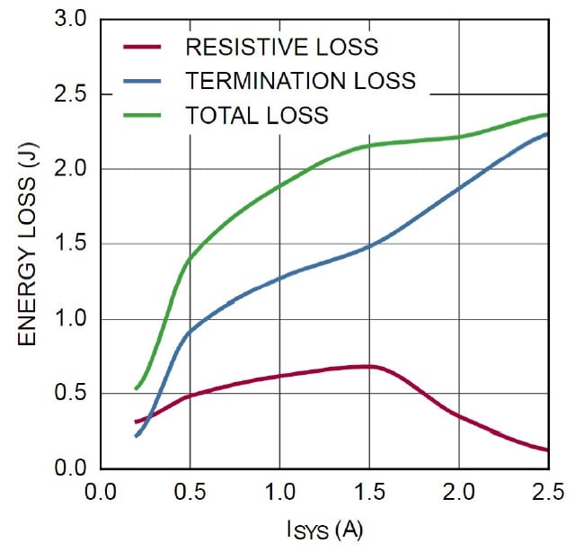 Energy Loss Due to ESR at Various VSYS Loads (Single 10F, Boost to 5V)
Supercapacitor Leakage
Internal leakage in a supercapacitor is comprised of diffusion current and steady-state leakage current. Diffusion current decreases as the supercapacitor is held at a voltage. Manufacturers typically specify leakage at a certain time after the supercapacitor has been charged.
The 10F supercapacitors on the DC2642A have a specified leakage current of 0.023mA after 72 hours of being held at the rated charge voltage. Near the start of charging, though, the leakage current is significantly higher. Supercapacitor leakage is primarily a concern for backing up loads for a longer time. To test operation with worst-case leakage current, charge a supercapacitor and trigger a power-fail immediately after the supercapacitor reaches its full charge voltage.
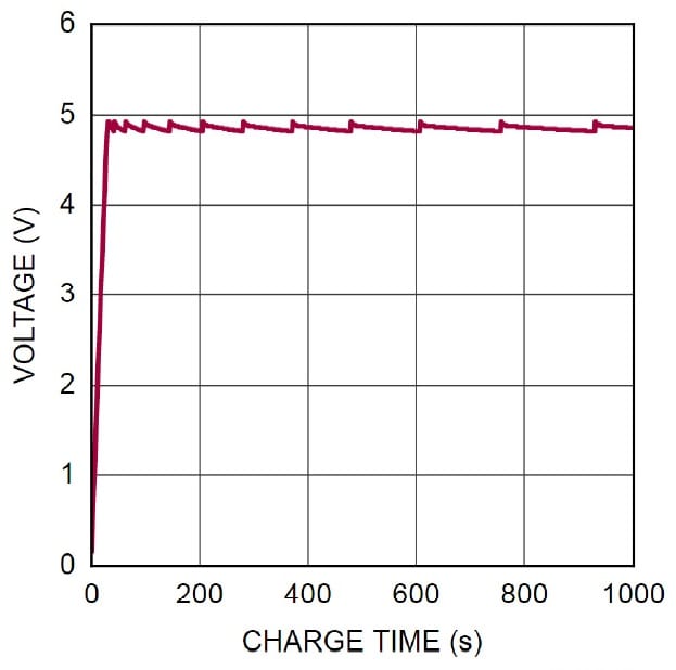 Supercapacitor Recharge Rate Due to Self-ischarge (Dual 10F, Unloaded)
The figure above shows the self-discharge of the supercapacitor triggering a recharge cycle. Note that the recharge cycles become less frequent as the supercapacitor remains near full charge.
Keeping these factors in mind, the LTC4041 can be used to design a robust 5V backup system using either a single supercapacitor or two supercapacitors in series. Given the effects of the switch current limit and the ESR of the supercapacitor model, using two supercapacitors in series is generally preferable when operating at higher load currents. However, designs with lower load currents can save space and lower costs by using a single supercapacitor.