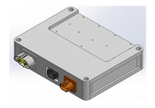
Transphorm Unveils 4kW Evaluation Board for Single-Phase AC-to-DC Power Conversion
The TDTTP4000W065AN employs bridgeless totem-pole power factor correction topology with traditional analog control.
Bridgeless totem-pole power factor correction (PFC) topology enables the TDTTP4000W065AN to achieve high conversion efficiency. Analog control eliminates the need for the time consuming firmware development required when using digital signal controllers (DSCs).
Transphorm’s TDTTP4000W065AN evaluation board. Image courtesy of Transphorm
What is Totem-Pole Technology?
As illustrated below, totem-pole technology involves two GaN FETS (Q1 and Q2) employed with two low-resistance silicon MOSFETs (SD1 and SD2). This arrangement serves to to avoid the inefficiencies caused by the diode voltage drops characteristic of bridge rectification.
Simplified diagram of a Bridgeless totem-pole PFC Boost Converter. Image used courtesy of Transphorm
The GaN FETs employed, Transphorm’s TP65H035G4WS, are used in the fast-switching leg of the circuit (Q1 and Q2). These two are triggered at 65 kHz, while the two low-resistance MOSFETs in the slow-switching leg of the circuit (SD1 and SD2) are triggered at line speed (50Hz/60Hz).
During the positive part of the AC cycle, S1 is on and S2 is off; the opposite is true during the AC cycle’s negative part. Depending on the polarity of the AC input, one GaN FET allows energy intake by the boost inductor, while the other serves as a slave switch to release energy to the DC output. When the polarity changes, the roles of the two GaNs also changes. Thus, the GaN FETs form the basis of a boost converter.
A dead time, where both GaN FETs are momentarily turned off, is inserted between switching events in order to avoid shoot-through. To allow for continuous conduction mode (CCM) operation, the body diode of the GaN FET serves its turn as the slave functions as a flyback diode, allowing inductor current to flow during dead time.
Advantages of Analog Totem Power Converters
As mentioned, with analog control there is no need to deal with programming DSC firmware. Another advantage for analog solutions is that they require less standby power than do digital units based on digital signal processors (DSP). This can be important if the unit to ultimately be powered by the power converter spends significant time in stand by.
In some cases, system design may call for the added flexibility of a digital solution. For those applications, Transphorm’s previously released TDTTP4000W066C evaluation board is an option. Also a 4 kW AC-to-DC bridgeless totem-pole PFC employing TP65H035G4WS FETS, this unit incorporates a dsPIC33CK DSC board from Microchip. The Microchip device is preprogrammed, and is offered with dedicated firmware support.
“Transphorm’s analog evaluation board provides an unprecedented opportunity to access our highly efficient GaN in the easiest way possible. Much like the preceding digital board, it gives power system engineers a choice that the high voltage device market was previously lacking,” said Philip Zuk, VP of Worldwide Technical Marketing and NA Sales, Transphorm. “Regardless of the end application’s targeted value proposition, we have the diverse toolset and the most robust GaN possible to help you succeed.”
Key Attributes of the TDTTP4000W065AN
The device operates with a 99.1% efficiency at 1220 watts.
Image used courtesy of Transphorm
The TDTTP4000W065AN can operate with an input voltage ranging from 47 to 63 Hz. Maximum input power is 2000W at 115 VAC or 4000W at 230 VAC. Output voltage is 387 VDC +/-5 VDC.


