Facebook
 Google
 GitHub
 Linkedin
TDK’s Single-Phase EMI Filters Target Conducted Emissions
The filters have insertion losses of 80 dB in differential mode and leakage currents below 2 mA. This article will review EMI on power lines, the purpose of EMI line filters, and the TDK series of products.
Electromagnetic compatibility (EMC) ensures devices operate as intended within their electromagnetic environment without introducing intolerable electromagnetic disturbances to other nearby devices. Conducted emissions are a major form of EMC.
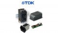
Recently, TDK released a series of single-phase EMI line filters designed to help minimize the impact of conducted emissions for AC and DC applications.

A B84742A*R725 series filter. Image used courtesy of TDK
EMI on Power Lines
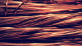
Electromagnetic interference (EMI) on power lines occurs for several reasons.
Electronic devices typically switch electrical currents on and off rapidly, a process that inherently generates electromagnetic waves. These can propagate along power lines and cause interference with other devices within the same electrical network. This is known as conducted emissions. As defined by the FCC and UL, conducted emissions for commercial and industrial equipment must be kept below certain thresholds in the 150 kHz to 30 MHz range.

An example of a conducted emissions test. Image used courtesy of The EMC Shop
If not accounted for, this interference can manifest as noise in audio equipment, malfunctions in precision devices, or data corruption in digital equipment. The consequences of EMI can be significant, ranging from minor annoyances in consumer electronics to potentially catastrophic failures in critical systems like medical equipment or aviation controls. In industrial settings, EMI can lead to downtime and loss of productivity due to equipment failure or malfunctions.
EMC Line Filters
EMC line filters, or EMI filters, counteract these issues by preventing the transmission of high-frequency electromagnetic noise between electronic devices and the power supply.
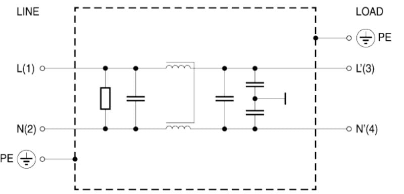
A typical circuit diagram of a single-phase EMC filter. Image used courtesy of TDK
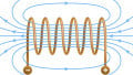
They use a combination of inductors and capacitors to create a low-pass filter, which allows low-frequency signals to pass while blocking high-frequency noise. The inductors impede the flow of high-frequency currents, while the capacitors provide a short-circuit path for the noise to ground or back to the source, thereby preventing it from affecting downstream devices.
These filters are often classified by their attenuation-frequency characteristic graphs, which show how much attenuation the filter can achieve at different frequency ranges and in different configurations. Properly designed and installed, EMC filters are highly effective at mitigating EMI, ensuring the reliability and efficiency of electronic systems, and complying with international EMC standards.
The B84742A*R725 Series of EMC Filters
TDK’s B84742A*R725 series of single-phase EMC filters are designed to cater to both alternating current and direct current applications. Every filter has a voltage rating of up to 250 V, with varying offers ranging in rated current from 6 A to 30 A. Notably, these filters also impress in terms of size and weight, with each family offering a 7 x 60 x 34.5 mm footprint and weighing between 200 g and 310 g.
TDK states these filters deliver exceptional performance, with a unique emphasis on high insertion loss and low leakage currents. The device can achieve differential mode insertion loss up to near 100 dB at frequencies exceeding 10^7 Hz, with common mode insertion loss reaching above 70 dB at the same frequencies. The same datasheet shows leakage currents beneath 2 mA, which TDK says is particularly crucial in preventing the unintentional tripping of residual current devices (RCDs), a common issue that can lead to unnecessary downtime and maintenance challenges.
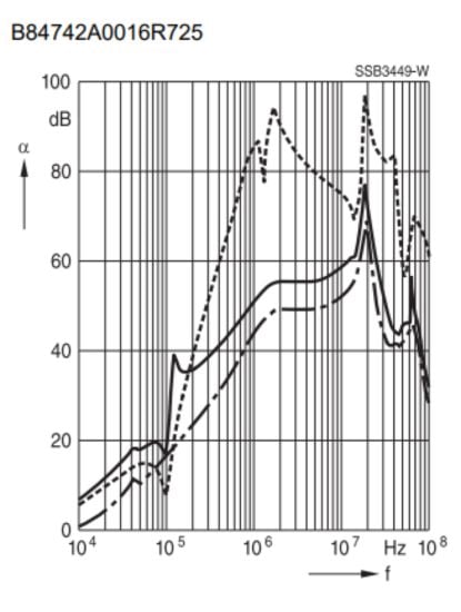
The insertion loss versus frequency characteristic of the B84742A0016R725. Image used courtesy of TDK
Finally, the B84742A*R725 series can withstand the rigors of industrial environments, with UL approval and an operational temperature range of up to 55°C.
Another Solid Option for EMI Filters
While many EMI/EMC line filters already exist on the market, TDK’s offerings are a solid option. With impressive insertion loss characteristics, low leakage currents, and pre-approval from UL for industrial environments, the B84742A*R725 series seems to be a solid plug-and-play option for anyone looking to minimize the conducted emissions of their device.