Facebook
 Google
 GitHub
 Linkedin
STMicroelectronics Debuts 200W SMPS Aimed at LED TV Applications
The new switched mode power supply (SMPS) surpasses even the toughest efficiency and standby power requirements.
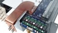
The STEVAL-NRG011TV board from STMicroelectronics (ST) is based on the company’s venerable STNRG011 digital PFC (power factor correction) and resonant LLC converter. The board’s purpose is to help engineers more quickly build complete power supplies for LED and OLED televisions.

The STEVAL-NRG011TV board. Image courtesy of ST
The STEVAL-NRG011TV is an evaluation board that exploits the proven and reliable topology of the STNRG011 to enable adjustment and optimization to attain maximized performance. With the required digital control algorithms permanently etched into the controller’s ROM, no programming is required of power supply designers. Additionally, a set of sample parameters is stored in the board’s user-programmable non-volatile memory (NVM).
The STEVAL-NRG011TV
The STEVAL-NRG011TV is an evaluation board that operates from inputs ranging from 90VAC to 264VAC. With inputs of either 115VAC or 230VAC, the unit achieves full load efficiencies of over 91%. A 12VDC, 4A regulated output is primed for the TV’s controller and audio subsystem. A separate 65VDC, 4A output is tasked with powering the TV’s LED display’s backlighting. Both outputs are non-isolated.
The STEVAL-NRG011TV is essentially a two-stage AC/DC SMPS. The front-end is a transition mode PFC pre-regulator feeding into and controlling a second stage LLC HB resonant converter. The power supply evaluation board consumes only 120mW from the AV power main during periods of no load.
The STNRG011
The heart of the STEVAL-NRG011TV is the highly integrated STNRG011 IC. The latter features an 8-bit CPU subsystem, an analog-to-digital converter (ADC), and control logic including PFC and LLC event-driven state machines (SMEDs). The STNRG011 also provides for power management, protections, and high voltage startup circuitry.
The STNRG011’s multi-mode PFC controller features both transition-mode and discontinuous-conduction mode (DCM) capabilities. It also includes a high-voltage double-ended controller for the LLC resonant half-bridge and a startup generator rated to 800V as well as a digital engine to ensure optimal operation.

Simplified block diagram of the STNRG011. Image courtesy of the datasheet.
Communication with an external EEPROM, which can hold needed software updates. is handled via a two-wire UART interface. Through this channel, remote monitoring can be achieved.
The save power during light load conditions, the IC features a flexible burst mode that is user-programmable.
STNRG011 Maximums
- The IC can control up to 800 volts
- The IC itself operates with a maximum supply voltage of 19 volts
- VCORE, for the power management and communications subsystem can be up to 5.5 volts
- Maximum thermal resistance from junction to ambient is 120°C/W
STNRG011 Operating Electrical Characteristics
Typical VCC processing turn-on and turn-off voltages:
- Processing turn-on threshold Voltage rising is 17V
- Processing turn-off threshold Voltage falling is 8.7V
Typical VCC thresholds for Vcore turn-on and turn-off
- VCC threshold for Vcore turn-on with voltage rising is 8V
- VCC threshold for Vcore, turn-off with voltage falling is 7V
Complete information on the STNRG011 can be found on the device’s datasheet.
Physical Considerations for The STNRG011
- The STNRG011 is available in a 20-pin SO20 package with approximate dimensions of 0.5 inches by 0.4 inches (including gull wings)
- It operates over a junction temperature range of -40℃ to 150℃