Facebook
 Google
 GitHub
 Linkedin
Interleaved Boost Power Factor Correction Development Kit
When developing high-voltage applications, especially offline power factor correction (PFC) applications, engineers face safety concerns with high-voltage and high-energy electronic devices. The purpose of the Low-Voltage Power Factor Correction (LVPFC) development kit from Microchip Technology is to offer safe voltage levels at moderate power, while designing algorithms for a boost PFC topology.
These algorithms can be applied on real systems under development with minimal effort. The LVPFC development kit utilizes Microchip's latest Digital Power Plug-In Module (DP PIM) with the dsPIC33EP128GS806 device, supporting fully digital and advanced power control algorithm schemes. However, the pinout is standardized and the kit supports all currently available DP PIMs, thus allowing users to evaluate different devices under the same conditions.
The LVPFC Development Board is based on conventional Interleaved Boost Power Factor Correction (PFC) topology. The converter supports a 24Vac input, but the PCB is designed following high-voltage design rules. With some modifications, the board can support a universal offline voltage range of 80Vac to 260Vac, and up to 200W output power at 400Vdc output voltage.
The LVPFC Development Kit consists of:
- LVPFC Development Board
- Digital Power Plug-In Module (DP PIM) Board
Optional supporting equipment:
- Isolation Transformer
- Active Load 50W
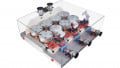
 LVPFC development kit (click on diagram to enlarge)
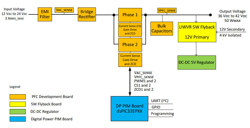
The main blocks of the LVPFC development board are:
- EMI/EMC filter at the input (capable of high voltage)
- Bridge rectifier (3A maximum, capable of high voltage)
- Phase 1 (MOSFET, current transformer, diode rectifier)
- Phase 2 (MOSFET, current transformer, diode rectifier)
- Ultra-wide voltage range (UWVR) 5W flyback (capable of low and high voltage); provides a 12V primary, non-galvanic isolated and 12V secondary, 4kV galvanic isolated voltage
- Switch mode step-down regulator, 5V/400 mA, pin-to-pin compatible with the LAN780X family of linear regulators
The LVPFC development board supports:
- Single-phase or dual-phase operation modes
- Discontinuous, transition, & continuous current modes of operation
- Input ac voltage, output dc voltage: resistive voltage divider sense
- Current sense in each power switch leg: current transformers
- Zero-cross detection (ZCD): auxiliary winding placed at storage chokes
- Inrush current limiter: negative temperature coefficient (NTC) resistor and relay
- Output overvoltage protection (OVP): analog comparator with hysteresis and disabling gate drivers; power reset (unplug the power) is needed to reset the comparator
- Mating socket for DP PIM board
The LVPFC Development Board has the following features (as shown in the figure below):
 LVPFC development kit circuit board (click on image to enlarge)
- Socket for Digital Power Plug-In Module (DP PIM) boards. Socket type is Samtec, Inc. (Part #: MECF-30-01-L-DV-WT)
- Auxiliary power supply module
- Input power connector
- Output power connector
- Input EMI filter
- PFC storage chokes
- Current transformers
- Output bulk capacitors
- Input rectifier, power MOSFETs with their heat sink
- Inrush current limiter (NTC resistor and relay)
- DC-DC 5V regulator
Board dimensions are: 160mm (length) x 100mm (height).