Facebook
 Google
 GitHub
 Linkedin
Increasing Power Density of 4.5 kV IGBT Power Modules
This article demonstrates how a 4.5 kV power module can fulfill converter requirements in applications like railways, medium-voltage drives, and electric power systems.
This article is published by EE Power as part of an exclusive digital content partnership with Bodo’s Power Systems.
The requirements for future power-electronic converters are increasing constantly. Power density and converter efficiency have to increase further so output power will be adaptable for various projects and end users.
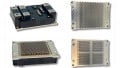
In 2020, Mitsubishi Electric announced the availability of HV100 power modules with an X-Series chipset and a voltage rating of 3.3 kV [1]. The HV100 package, as shown in Figure 1, offers high flexibility by easy parallel connection, low commutation stray inductance, and 10.2 kV isolation voltage. Offering such features, this package has been originally designed to fulfill the requirements of future railway converters [2]. Most recently, Mitsubishi Electric released another HV100 power module (CM450DE-90X), rated for 4.5 kV, that achieves a nominal current rating of 450 A.
This article introduces the CM450DE-90X, explains the advantages compared to previous power modules, and discusses key features for applications like railways, medium-voltage drives, and electric power systems.

Figure 1. Power module in HV100 package. Image used courtesy of Bodo’s Power Systems [PDF]
Inside CM450DE-90X, Mitsubishi Electric uses its latest 4.5 kV X-Series chip generation, including CSTBTTM (III) and RFC diode to ensure low losses, smooth switching waveforms, and high robustness in case of overcurrent.
The structure of the HV100 package is shown in Figure 2. The two DC terminals are located on one side of the power module, whereas two AC terminals are located on the opposite side. It allows a low-inductive connection of the DC-link capacitor and a clean converter setup. In its center, the HV100 offers space for the gate-driver board. When HV100 power modules are connected in parallel, terminals are still easy to access and well-sorted. For the gate driver in parallel connection, a PCB may be mounted just on top of the paralleled modules and control all of them. Also, such a design can be easily scalable by increasing (or decreasing) the number of paralleled modules to adjust the output power.
The HV100 package uses the MCB (metal casting direct bonding) baseplate. It allows lower thermal conductivity for remarkable power density. Compared to a classical package structure with an AlSiC baseplate, the thermal resistance from the junction to the case is about 30% lower with an MCB baseplate. Moreover, the MCB baseplate avoids substrate solder, which was originally a limiting factor of a thermal-cycling lifetime in conventional power-module packages.
Increased Power Density
The achievable output power of CM450DE-90X is compared with conventional 190 x 140 mm² power modules. The comparison considers, for example, two CM1350HG-90X single modules in conventional packages with three paralleled CM450DE90X dual modules, which corresponds to the same nominal current rating for one half-bridge. Even though the nominal current rating is the same, Figure 3 shows that the HV100 power modules occupy about 20% less area on the heatsink.
Stray inductance between the dc-link and the semiconductor chips is one of the main characteristics of a power module, which can influence significantly its switching behavior. High parasitic inductance protracts turn on and off processes as well as leads to higher overvoltage spike during turnoff. Both mentioned phenomena overall increase switching losses of the module. Since the HV100 achieves lower stray inductances, faster switching speeds and lower switching losses are enabled. Compared to the conventional package, the 4.5kV HV100 can reduce total inverter losses by 17% in acceleration mode (i.e., positive power factor Figure 4a) and 18% in braking mode (i.e., negative power factor Figure 4b) [3].

Figure 2. Cross-section view of HV100 power module, including MCB baseplate structure. Image used courtesy of Bodo’s Power Systems [PDF]

Figure 3. Size comparison for one half-bridge with HV100 and conventional packages at the same nominal current rating. Image used courtesy of Bodo’s Power Systems [PDF]
Using MelcoSim ver.5.4.1 [4], the achievable output current is calculated for three CM450DE-90X in parallel compared to CM1350HG90X and CM1200HG-90R (previous R-Series). The results are shown in Figure 5. Compared to the previous R series HVIGBT modules, the X series can contribute to lower losses, improved thermal resistance, and increased maximum allowed operating temperature to Tj=150°C. The possible output current in the CM1350HG-90X module might be increased by around 17% in comparison to CM1200HG-90R. A further 12% increase may be achieved by using new HV100 dual modules CM450DE-90X (three in parallel). This is achieved by the lower switching losses and the improved thermal resistance due to the MCB baseplate.

Figure 4. Inverter Loss Calculation Result. Image used courtesy of Bodo’s Power Systems [PDF]

Figure 5. Relationship between output current and carrier frequency for R series HVIGBT, X series HVIGBT and 4.5kV HV100 (Condition: Sinusoidal, VCC=2800 V, PF=+0.85, M=1, TS=80°C, Tj = Tjop). Image used courtesy of Bodo’s Power Systems [PDF]
Parallel Operation
The HV100 package is designed for simpler parallel connections. Hence, even for parallel connections, the terminal layout allows straight forward connection of the dc-link capacitors and the AC output. In the following, the current sharing among two parallel-connected CM450DE-90X is measured. Figure 6 shows the test setup. With it, the individual currents of the N-side IGBTs are measured. The tests have been performed at room temperature, VCC = 2800 V, a total current of IC,total = 900 A (450 A per power module), and a gate voltage of VGE = ± 15 V.
Figures 7 (a) and (b) show the current sharing between the two power modules during turn-off and turn-on, respectively. The measurements show the current is distributed evenly between the two power modules, leading to good utilization of the available chip area.
It should be noted that the two modules used in the evaluation have been selected to have small differences in their individual characteristics. Regarding the influence of power module parameter variations on the parallel connections [5].
Switching With High Stray Inductance
Switching with low DC-link stray inductance LS is recommended to reduce switching losses and overvoltage during turn-off switching. However, a converter design with low LS might not always be possible. In some cases, for example, in multi-level converters, the power module should also be able to operate safely even under higher LS conditions. Figure 8 shows a comparison of switching waveforms at LS=100nH and 400nH for 4.5kV HV100 during turning-off. As can be seen, even at LS high as 400 nH, the maximum VCE voltage reaches only around 3600V. For further measurement results at high stray inductance, please see [3]. In summary, CM450DE-90X can operate even with high stray inductance having enough margin to VCES and without oscillations.

Image used courtesy of Bodo’s Power Systems [PDF]

Figure 7. Current sharing of two parallel-connected CM450DE-90X (Conditions: VCC=2800V, IC,total=900A, VGE=±15V, Tj =25°C, N-side). Image used courtesy of Bodo’s Power Systems [PDF]

Figure 8. Comparison of switching waveform of 4.5kV HV100 between Ls=100nH and Ls=400nH (Condition: VCC=2800V, IC=450A, VGE=15 V, Tj =150°C). Image used courtesy of Bodo’s Power Systems [PDF]
Ruggedness in Overcurrent Events
Power module robustness is one of the main required features, especially for such responsible applications as railway or electric power systems. Defining RBSOA (reverse bias safe operation area) is the typical approach to evaluating the robustness of the IGBT module. This characteristic shows the ability of a power module to withstand certain voltage and current during IGBT turn-off. In Figure 9, the specified RBSOA for CM450DE-90X is shown in black color. In the same picture, real type-test measurement results are shown in orange. It has been confirmed that the CM450DE-90X sample has not failed even at 2700 A, which is a 6-times-rated current. This difference demonstrates the ruggedness of CM450DE-90X and potentially gives additional safety margin to the converter manufacturers and end-users in case of unexpected over-current events.

Figure 9. Specified RBSOA and evaluation result (VCC=3400V, Tj =150°C). Image used courtesy of Bodo’s Power Systems [PDF]
Table 1. Line-up of HV100 and LV100 power modules.

HV100 Power Modules
The new 4.5 kV/450 A power module in the HV100 package provides 10.2 kV isolation voltage and remarkable performance enabled by its MCB baseplate and latest chip generation. CM450DE-90X fulfills future converter requirements. In particular, power-density increase, simple parallel connection, and high ruggedness in case of overcurrent have been discussed.
The CM450DE-90X is extending the line-up of the LV100/HV100 product family. Besides CM450DE-90X, there are additional power modules for 1.7 kV and 3.3 kV rated voltage available. Table 1 shows the complete LV100 / HV100 line-up.
References
[1] Mitsubishi Electric Corporation, Mitsubishi Electric to Launch HV100 dual type X-Series HVIGBT Modules, Tokyo, Japan, 2020.
[2] N. Soltau, E. Wiesner, R. Tsuda, K. Hatori and H. Uemura, “Demands by Future Railway Converters and How They Change Power Semiconductor Modules,” in Bodo’s Power Systems, Jul 2021.
[3] K. Mikami, K. Hatori and N. Soltau, “4.5 kV HV100-type HVIGBT Module for Large Industrial Equipment,” in PCIM Europe, Nuremberg, Germany, 2023.
[4] Mitsubishi Electric Corporation, “Mitsubishi Electric Power Module Loss Simulator Melcosim,” [Online]. Available: https://www.mitsubishielectric.com/semiconductors/simulator/index.html. [Accessed 19 May 2023].
[5] Y. Ando, J. Sakai, K. Hatori, N. Soltau and E. Wiesner, “Influence of IGBT and Diode Parameters on the Current Sharing and Switching-Waveform Characteristics of ParallelConnected Power Modules,” in 24th European Conference on Power Electronics and Applications (EPE’22 ECCE Europe), Hanover, Germany, 2022.
This article originally appeared in Bodo’s Power Systems [PDF] magazine and is co-authored by Nils Soltau and Victor Tolstopyatov of Mitsubishi Electric Europe BV, Ratingen, Germany, and Kazuto Mikami and Kenji Hatori of Mitsubishi Electric Corporation, Fukuoka, Japan.