 Facebook
 Google
 GitHub
 Linkedin
Parasitic Inductance
What is inductance?
Electric inductance is a property of all conductors. A change in the current flowing through the conductor creates (induces) a voltage in that conductor, as well as all nearby conductors. The induced voltage opposes the change in the current that induced the voltage. Inductance is a consequence of two laws of physics. Firstly, a constant current flowing through a conductor creates a constant magnetic field. Secondly, a variable magnetic field induces a voltage in all nearby conductors, including the conductor which was used to create the magnetic field in the first place. When these two laws are combined, the resulting effect is inductance. Just like resistors are used to introduce a desired resistance in a circuit, and like capacitors are used to introduce a desired capacitance, inductors are electrical elements used to introduce a desired amount of inductance into the circuit. The inductance formula for an ideal solenoid (a coil of wire) wound around a cylindrical body of material is given as:
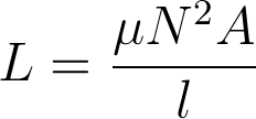
where L is the inductance, µ is the magnetic permeability of the material used in the inductor, A is the cross-sectional area of the coil and l is the length of the solenoid (not the length of the wire, but the longitudinal dimension of the coil).
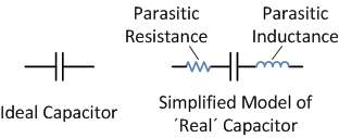
An ideal capacitor has no resistance and no inductance, but has a defined and constant value of capacitance. The unit used to represent inductance is henry, named after Joseph Henry, an American scientist who discovered inductance.
Parasitic inductance
Parasitic inductance is an unwanted inductance effect that is unavoidably present in all real electronic devices. As opposed to deliberate inductance, which is introduced into the circuit by the use of an inductor, parasitic inductance is almost always an undesired effect. There are few applications in which parasitic inductance is actually a desired effect, such as helical resonators which can be used as filters. Just like all other real elements used in electronics, such as resistors or even connecting wires, capacitors exhibit this effect as well.
In order to understand the impact of parasitic inductance on a capacitor, one must first grasp the concept of reactance.
Reactance
In a DC circuit, every element can be described by its resistance. Resistors have a certain fixed amount of resistance, R. Capacitors in DC circuits can be regarded as elements with an infinite resistance (no current flowing through a capacitor), while inductors can be regarded as short connections (no voltage drop across an inductor) in a DC circuit.
AC circuits, however, are different. Each element in an AC circuit can be described by its impedance. Impedance is a measure of just how much an element “impedes, or opposes, current flow when a fixed-amplitude variable voltage is applied across its terminals.
Impedance can be further divided into two parts, called resistance and reactance. Applying a variable voltage across a purely resistive component (a resistor) in an AC circuit will result in a certain amount of alternating current flowing through the element, and this current will be in phase with the voltage. Applying a variable voltage to a purely reactive component in an AC circuit will result in an alternating current through the element, but this current will be ±90 degrees out of phase compared to the voltage, depending on which element is used - a capacitor or an inductor. Namely, the voltage across a capacitor lags behind the current by 90 degrees, while the current through an inductor lags behind the voltage across the inductor by 90 degrees. The formula for impedance is given as:
![]()
where Z is the impedance, R is resistance and X is reactance. It is worth noting that impedance is a complex number, whose real part is the resistance, and imaginary part is the reactance.
Ideal capacitors and inductors are purely reactive components, and they influence only the reactive, imaginary part of impedance. However, they do so in distinct ways. The reactance of a capacitor is given as:
![]()
where ω is the angular frequency (ω=2pf, where f is the frequency of the signal), and C is the capacitance. On the other hand, the reactance of an inductor is given as:
![]()
where L is the inductance of the inductor. It should be noted that the reactance of a capacitor is a negative value and the reactance of an inductor is a positive value.
The effect of parasitic inductance on a capacitor
As previously indicated, the reactance of a capacitor is of opposite sign than the reactance of an inductor. This means that any parasitic inductance present on a capacitor will reduce the impedance of that capacitor by a certain amount. To illustrate this, consider the following formula:
![]()
where Z is the impedance of a capacitor exhibiting parasitic inductance (but not exhibiting parasitic resistance). Let’s analyze this formula in order to understand the effect of parasitic inductance on a capacitor.
Let’s assume an angular frequency of 1Mhz (approx. 6.2·106 rad/s), a capacitance of 0.1 µF and a typical parasitic inductance for ceramic capacitors, approximately 1nH. In the absence of any parasitic effects, the impedance of such a capacitor would be approximately -j·1.591 Ω. If parasitic effects are considered, the impedance is now -j·1.585 Ω. Not a big deal, since the effective impedance is only 0.37% less when a parasitic inductance is present.
However, at larger frequencies, parasitic inductance becomes a bigger problem. Let us now increase the frequency to 10MHz and repeat the calculation. The angular frequency is now approximately 6.2·107 rad/s. In the absence of parasitic effects, the impedance of a 0.1 µF capacitor would be approximately -j·0.1591 Ω. If we introduce parasitic impedance, the impedance is now -j· 0.0963 Ω. The effective impedance is now reduced by 40%! At higher frequencies, this becomes an increasing problem and at some point the impedance becomes positive and the capacitor in facts starts acting like as an inductor.
For this reason, there are low inductance capacitors specially made for high frequency applications and for applications where parasitic effects are highly undesirable. They are made using special materials and packaging with leads made as short as possible. In order to reduce inductance further, the internal layout of a capacitor is designed to cancel out all magnetic fields generated by the capacitor current.