Facebook
 Google
 GitHub
 Linkedin
Sizing Overload Protection for Motors Above 1 HP
Learn the rules for sizing overload protection for motors above 1 hp.
A motor delivering more than its rated horsepower will consume more current and overheat, which may burn out the unit. Part III of the National Electrical Code requires overload devices to disconnect the motor if the overload is large and long enough to harm the piece. The overload device will also disconnect the motor if it fails to start.
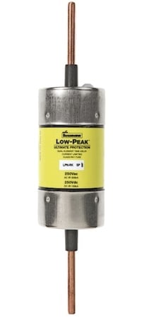
Image used courtesy of EATON
Part III Motor and Branch-Circuit Overload Protection
According to Article 100 of the National Electrical Code “Definitions,” an overload is the operation of equipment above its full-load rating or a conductor over its rated ampacity that would cause damage or dangerous overheating when it persists for a sufficient time.
The Code dictates rules regarding the sizing of the overcurrent device for protection against motor overload. The rules aim to protect the elements of the branch circuit, including the motor itself, from excessive heating due to motor overload. The overload ranges from above the full-load current up to and including the locked rotor current. If the overload persists for a sufficient time, it will damage or produce dangerous overheating of the apparatuses.
- Short circuits and ground faults are overcurrents but not overloads.
Fuses, circuit breakers, and particular overload relays provide overload protection.
Dual-element, time-delay fuses are practical for motor applications because they provide overload, short-circuit, and ground-fault protection.
During the starting period–a few seconds–a motor consumes a current several times its rated value. After that, the current drops to a value often below the rated current figure, depending on the motor’s load.
An ordinary fuse will most likely blow during this starting period. Time-delay fuses do not blow fast like ordinary fuses on large brief overcurrents but do blow on small continuous overloads and instantly under short-circuit and ground-fault conditions.
Figure 1 shows one location for the motor overload protection in a motor branch circuit.

Figure 1. One location for the motor overload protection in a motor branch circuit. Image used courtesy of Lorenzo Mari
National Electrical Code Section 430.31 General
Part III rules the overload devices to protect motors, motor-control apparatus, and motor branch-circuit conductors against overloads and failure to start.
Section 430.31(A) Where Hazards Exist
- Do not apply the provisions in Part III where the power loss caused by the overload protection would produce a hazard.
- A typical example of this situation is fire pumps. Article 695 contains detailed requirements for the installation of fire pumps.
- NFPA 20, “Standard for the Installation of Stationary Pumps for Fire Protection,” provides in-depth requirements for selecting and installing fire pumps.
There is no requirement to provide overload protection to fire pumps. When dealing with a significant contingency, it would be impractical to shut down fire pumps due to an overload. However, they require short-circuit and ground-fault protection to prevent these faults from worsening the situation.
Section 430.31(B) Not Over 1 kV
- Do not apply the provisions in Part III to motor circuits rated above 1 kV.
- See Part XI for cases above 1 kV.
National Electrical Code Section 430.32 Continuous-Duty Motors
Section 430.32(A) More Than 1 HP
- Protect against overload by one of the methods in sections 430.32(A)(1) through (4).
Section 430.32(A)(1) Separate Overload Device
- Select the device to trip at no more than the following percentages of the motor full-load current rating marked on the nameplate:
Motors with a marked service factor 1.15 or greater………………125%
Motors with a marked temperature rise of 40°C or less…………...125%
All other motors………………………………………………………...115%
- Motors not marked with a service factor or temperature rise are classified as “all other motors.”
Note that this rule requires using the motor nameplate full-load current to select the overload protection rather than the full-load current values from Tables 430.247 through 430.250.
You need to know the service factor and the temperature rise ratings of the motor to apply this table.
Motor nameplates have stamped a “service factor” between 1.00 and 1.35. A service factor of 1.00 means that a motor located in a place where the ambient temperature is not above 40°C can supply its rated horsepower continuously without damage.
If the service factor is 1.15, you may use the motor up to 1.15 times its rated hp under the same conditions. Multiply the rated hp by the service factor to get the maximum motor output without causing overheating.
The service factor provides temporary extra power–a safety margin where the load may peak slightly above the rated value–but the motor operates more efficiently and lasts longer if it works at its rated horsepower or less.
Example 1: What’s the maximum output of a 5 hp motor with a service factor of 1.15?
Solution:
Multiply the rated hp by 115%.
5 hp x 1.15 = 5.75 hp
The temperature rise is the difference between the motor winding and ambient temperatures when running at rated load and voltage – this is also a safety margin. A motor with a temperature rise of 40° C will not warm up more than 40°C above its rated ambient temperature.
- If the temperature rise is not more than 40°C and the service factor is not less than 1.15, size the overload at 125% of the nameplate full-load current.
- If the temperature rise is greater than 40°C or the service factor is lower than 1.15, size the overload at 115%. This motor falls under the “all other motors” category.
Figure 2 shows a simplified arrangement employed in examples 2 through 7, which uses a dual-element, time-delay fuse for motor overload protection.
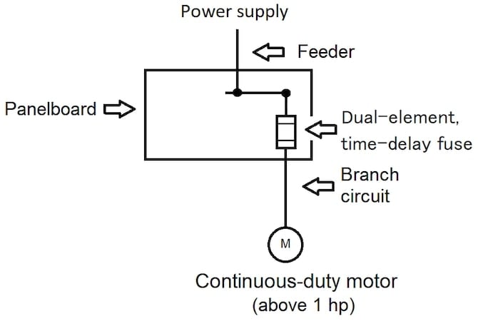
Figure 2. Set-up for examples 2 through 7. Image used courtesy of Lorenzo Mari
Example 2: Size the fuse for the overload protection of a single-phase, 3-hp, 115-V motor with a nameplate full-load current of 32 A and a temperature rise of 40°C.
Solution:
Multiply the nameplate full-load current by 125%.
32 A x 1.25 = 40 A
Use a 40 A dual-element, time-delay fuse per Table 240.6(A).
Example 3: Size the fuse for the overload protection of a single-phase, 3-hp, 115-V motor with a nameplate full-load current of 32 A and a service factor of 1.10.
Solution:
Categorize this unit as “all other motors.” Multiply the nameplate full-load current by 115%.
32 A x 1.15 = 36.8 A
Use a 35 A dual-element, time-delay fuse per Table 240.6(A)
Suppose the calculated value does not match a standard value or is insufficient to start the motor or maintain the load. Higher values are permitted but do not exceed the percentages indicated in Section 430.32(C), as follows:
Motors with a marked service factor 1.15 or greater………………140%
Motors with a marked temperature rise of 40°C or less…………...140%
All other motors………………………………………………………...130%
A device chosen according to the above percentages does not necessarily provide proper branch-circuit protection. In practice, tune the device as low as possible while still being able to carry the motor’s starting current.
Example 4: Verify if, in Example 3, the next higher fuse size is adequate.
Solution:
Multiply the nameplate full-load current by 130%.
32 A x 1.30 = 41.6 A
Using a 40 A dual-element, time-delay fuse in Example 3 is acceptable.
Example 5: Find the maximum fuse size for the overload protection of the motor in Example 2.
Solution:
Multiply the nameplate full-load current by 140%.
32 A x 1.40 = 44.8 A
Do not exceed this current value. Level down to the next smaller size and keep the 40 A fuse.
Example 6: Size the fuse for the overload protection of a single-phase, 3-hp, 115-V motor with a nameplate full-load current of 32 A, a service factor of 1.12, and a temperature rise of 41°C.
Solution:
Categorize this unit as “all other motors.” Multiply the nameplate full-load current by 115%.
32 A x 1.15 = 36.8 A
Use a 35 A dual-element, time-delay fuse per Table 240.6(A)
Sometimes, motor nameplate data are unknown during the design phase. In those cases, you may use data from Tables 430.247 through 430.250.
Example 7: Without knowing the nameplate data, find the maximum fuse size for the motor’s overload protection in Example 2.
Solution:
Enter Table 430.248 with 3 hp and read full-load current = 34 A in the 115-V column.
Multiply the full-load current by 140%.
34 A x 1.40 = 47.6 A
Do not exceed this current value. Level down to the next smaller size and use a 45 A fuse.
Section 430.32(A)(2) Thermal Protector or Electronically Protected
The Code approves thermal protectors integral with the motor and electronically protected motors.
- The ultimate trip current of a thermally or electronically protected motor must not exceed the following percentages of full-load currents listed in tables 430.248 through 430.250:
Motor full-load current 9 A or less……………………………………170%
Motor full-load current from 9.1 A to, and including, 20 A ………...156%
Motor full-load current greater than 20 A…..………………………...140%
Thermal and electronic protectors are sufficient protection against overload–no need for other means.
Section 430.32(A)(3) Integral With Motor
Suppose the motor is part of an approved assembly not habitually subjected to overloads. In that case, the NEC permits a protective device integral to the motor to safeguard against damage due to failure to start.
Section 430.32(A)(4) Larger Than 1500 HP
This section permits using embedded temperature detectors in motors rated above 1500 hp.
Temperature detectors are built into the motor and typically placed between the coil sides near the warmest region of the core. This method gives temperature readings closer to the maximum.
The output of the embedded temperature detectors interrupts the current to the motor when it reaches a temperature rise greater than marked on the nameplate at an ambient temperature of 40°C.
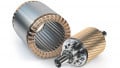
Figure 3 shows an example of a resistance temperature detector (RTD).
An RTD is a passive temperature sensing apparatus that takes advantage of the variation of a metal resistance with temperature.
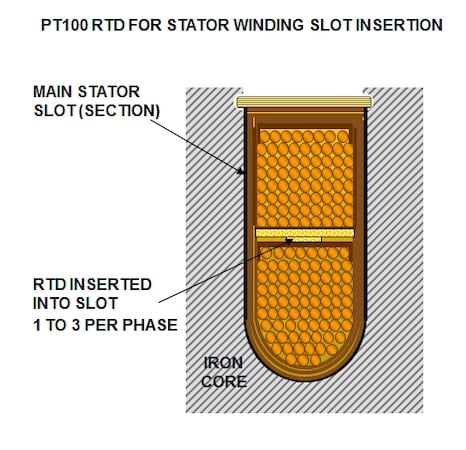
Figure 3. Winding RTD. Image used courtesy of Stamford-avk
Sizing Overload Protection Takeaways
- Overload protective devices help guard motors against burnout from occurrences causing a harmful excess of current, such as overloading, lack of oil, tight belts, worn bearings, single-phasing, and locked rotors.
- The overload protective devices secure not only the motors but also the controller, conductors, and other branch-circuit components.
- Device sizing must be per the percentages shown in sections 430.32(A)(1), (A)(2), and 430.32(C).
- Knowing the motor’s service factor and temperature rise is essential to applying the above percentages. If they are unknown, use the “all other motors” percentages.
- Sections 430.32(A)(1) and 430.32(C) require the nameplate current rating to size the motor overload protection.
- Section 430.32(A)(2) requires the full-load current given in tables 430.248, 249, and 250 to size the motor overload protection.