Facebook
 Google
 GitHub
 Linkedin
Optimized Thermal Layout for CIPOSTM Nano Half-Bridge Intelligent Power Modules
This article discusses PCB design considerations required to achieve the best thermal performance in a motor drive using CIPOS Nano half-bridge Intelligent
This article discusses PCB design considerations required to achieve the best thermal performance in a motor drive using CIPOS Nano half-bridge Intelligent Power Modules (IPM). We present an approach that uses thermal simulations with ANSYS Icepak software to create an optimized thermal layout. We show that the simulations are validated by experimental motor test results through temperature capture via a thermal camera. This paper targets intelligent power module application design engineers and PCB layout engineers who would like to obtain better system thermal designs in their final product.
Thermal Simulation
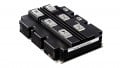
In a three-phase motor drive system, three half-bridge IPMs are needed. The placement of the three half-bridge modules on a PCB for optimal thermal performance is of interest to circuit designers. Four different placement configurations are explored. First, we did a thermal simulation on each of these configurations. Figure 1 shows the four configurations. In the simulation, we use the same copper area for each power pad, which is 1oz copper, 120mm2. To simplify the simulation and exclude other thermal impacts, we ignore peripheral components.

Figure 1. Four layout configurations
We ran simulations for two conditions of operation. For the light load condition, we assume each CIPOS Nano IPM has a power loss of 0.3W, and for full load condition, we assume each CIPOS Nano IPM has a loss of 1W. Table 1 shows the simulation results. Figure 2 shows both the light load and the full load simulation thermal images. From the simulation results, we can see that Option 2 is the optimal layout, which has the least temperature rise under the same power dissipation. At light load condition, it is 5ºC cooler than the regular layout in Option 1. At full load condition, it is around 10ºC cooler than Option 1.
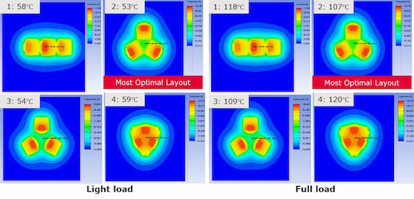
Figure 2. Light load and full load simulation results
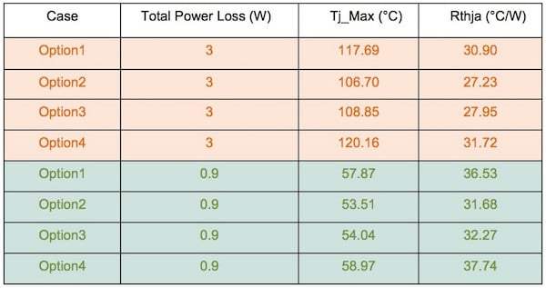
Table 1. CIPOS Nano thermal simulation results
Experimental Verification
The thermal simulation shows that PCB layout of three half-bridge CIPOS Nano IPMs affects thermal performance. We would like to confirm this finding to provide customers guidelines to optimize their PCB design. We made two different PCB layouts, which are Option 1 and Option 2, and tested them out under the same operating conditions. The results did confirm the findings of the simulations. Figure 3 shows the PCB layout of regular Option 1 and the optimal layout in Option 2.
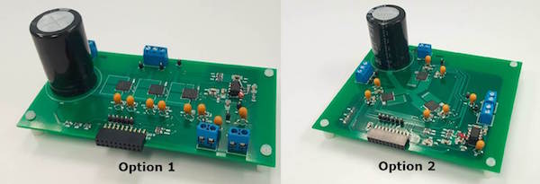
Figure 3. PCB layout of Option 1 and Option 2
The motor drive test conditions are as follows: switching frequency 6 kHz, 2-phase discontinuous SVPWM, DC bus voltage 300V, ambient temperature 25ºC, light load operation at 0.5Arms and 115W, and full load operation at 1Arms and 230W. Figure 4 shows the light load thermal images and the full load thermal images. The thermal images prove that Option 2 has better performance than Option 1: At light load and full load, Option 2 is 5ºC and 8ºC cooler, respectively.
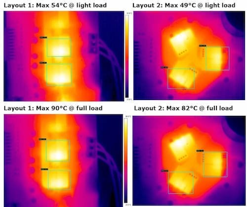
Figure 4. Light load and full load thermal images
Conclusion
In this article, several layouts have been proposed to see which one offers the best thermal performance when three half-bridge CIPOS Nano IPMs are used. Through both simulation and experiments, Option 2 is proved to be the best option with the lowest junction temperature when the same copper area and the same power are applied to each option. On the other hand, Option 2 can sustain higher losses or use smaller PCB area if the same junction temperature is required among different designs. In addition, Option 2 provides a circular layout which fits very well in applications where the motor drive board is required to be in that shape in order to be better embedded in the motor casing.
About the Authors
Pengwei Sun is a Staff Engineer, Technical Marketing and Applications at Infineon Technologies, El Segundo, C.A. He is in-charge of Electrical design of IPM schematics and layout. He earned both his Bachelor's Degree in Electrical Engineering and Master's Degree in Power Electronics and Motor Drive, Electrical Engineering at North China Electric Power University. He also took his Doctor of Philosophy (Ph.D.), Power Electronics, Electrical Engineering at Virginia Polytechnic Institute and State University.
Pei Jin works at Infineon Technologies.
This article originally appeared in the Bodo’s Power Systems magazine.